This page describes the DC powered filament extruder that was designed by MOST.
Note that calibration (described below) requires a GNU/Linux system and reasonable advanced knowledge of hard- and software. In particular, you need to know how to edit a program, how to compile a program for a standalone AVR microcontroller, and how to upload that program to the microcontroller. This page explains briefly how to do those things, but the explanations are not aimed at beginners.
The control board requires careful soldering. Ideally, a reflow oven would be used (a toaster oven can be used if proper care is exercised). Since the many of the components are surface mount, hand soldering is challenging. The following assumes the solder will be reflowed.
Set the DC-DC power supply output voltage to 5V. This MUST be done before soldering the DC-DC power supply to the control board. Attempting to set the voltage after it is soldered in place will destroy the ATMega AVR.
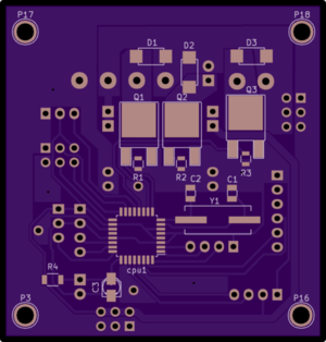
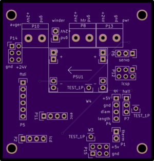
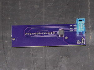
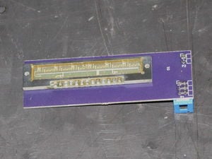
Front of control boardBack of control boardNote that components will be soldered on both the back and the front of the board.
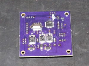
Front with SMD components soldered in place.Populate all the SMD components on the front of the board with solder paste and reflow the solder.
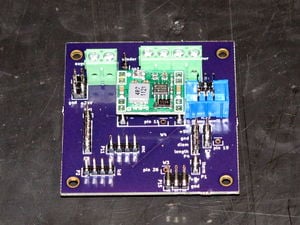
Back with components populated. Populate the back of the board with through-hole components.
The sensor has pads and holes that are smaller than the typical 0.1" (2.54mm) pitch pin headers DO NOT attempt to use a standard pin header and drilling out the sensor; they cost $30.
Solder SMD components to front of sensor board. Place the SMD components and reflow. Solder the 2x3 and 1x2 pin headers to the front of the board.
Solder linear array to board. Solder short pieces of copper wire into the back of the board and solder the TSL1406R sensor array to the copper wires..
Build and flash the firmware to the sensor's AVR (here).
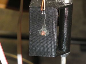
LED in shroud. Install the LED in the shroud with epoxy.
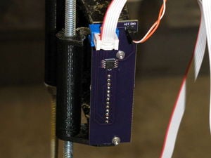
Sensor in shroud. Install the sensor in the printed shroud with two M3 x 12mm screws and washers. Connect the LED to the 1x2 pin header and plug the 6 conductor ribbon cable to the shrouded 2x3 pin header. Plug the other end of the ribbon cable into the icsp header on the controller board.
How to calibrate the DC filament extruder[edit | edit source]
This requires a GNU/Linux system and reasonable advanced knowledge of hard- and software. In particular, you need to know how to edit a program, how to compile a program for a standalone AVR microcontroller, and how to upload that program to the microcontroller. This page explains briefly how to do those things, but the explanations are not aimed at beginners.
You will need to get the library for your lcd display and put it in the libraries in your sketch book folder. You will need Arduino libraries from our GitHub and put that into your sketch book folder. Here is a link to Arduino libraries [1]. The library for your display may need to be chained depending on what it is doing.
The github repository contains all the sources in the firmware directory. The
firmware for the main board is in extruder, for the sensor is in sensor. The
code in sensor-graph is for the monitoring Arduino that is used to show the
measured data on screen.
If all the requirements are installed, everything can be built using the make
command. (Installing the arduino-mk package should pull everything in that you
need.) The code in extruder and sensor-graph should also be buildable from the
Arduino UI, but that may not work.
Firmware is uploaded using ICSP. We use a Beaglebone which connects four of
its digital pins and the 3.3V power to the ICSP connector. An avrdude
configuration file is required to make this work. Also, the avrdude version
from Debian Jessie (and earlier) has a bug that prevents it from working. This
has been fixed in Stretch. For an example of how this is done, see flash-bbb
and avrdude.conf in https://github.com/mtu-most/franklin/tree/master/server/.
When uploading firmware, the ICSP connector on the board that is programmed
must be used. This is the 6-pin shrouded header. The key of the header is
always on the side of the power.
We are using a usb connection to connect to the beagle bone so if you are not using a usb connection these commands will not work. You need to move the firmware from the computer to the beagle bone with " scp build-uno/extruder.hex debian@192.168.7.2: " command and than from the beagle bone to the machine with " sudo avrdude -C +avrdude.conf -c bbbmelzi -p atmega328p -U lfuse:w:0xe2:m ". This command will not run if you do not have this [2] from the franklin repository. You can put that on the beagle bone with this command " scp avrdude.conf debian@192.168.7.2: ".
For this, the computer needs to have
python-websocketd installed
(which requires python-network and python-fhs from the same place). The
firmware must be installed on an arduino, and a cable must connect all pins
between the ICSP header on the Arduino and the ISCP header on the sensor board.
The Arduino does not have a shrouded header; the key should be on the outside
of the board. If in doubt, measure which pins have 5V on them.
The server script needs to get the serial data from the Arduino on its standard
input. This means the port first needs to be set up, and then it must be given
to the server:
stty -F /dev/ttyACM0 115200 raw
./server < /dev/ttyACM0
Then use a browser to go to http://localhost:4567/. You should see a graph of
the sensor's measurement.
For the second step, the output of the regular firmware must be monitored.
This is done with the sensor-spy program. It is loaded on an Arduino similar
to the sensor-graph program, and it outputs the last received value of the
sensor to the serial port.
To use it, simply view the output of the serial port with:
cat /dev/ttyACM0
When moving a piece of filament through the sensor, it should change its value.
The senor firmware has two settings defined near the top that need to be
changed depending on your build. They are called SKIP and DELAY. The ouput
from the sensor should be approximately horizontal. In most of the sensor, it
is, but near the edges it goes down to zero. Because of this, the edges are
not used. SKIP defines how many pixels are skipped on both sides. Note that
the total number of pixels is 768, and it measures every 2^EACHBITS pixels, so
if you see something happen at pixel 20, and EACHBITS is 5, it's really pixel
20*32=640.
For monitoring, you may want to decrease EACHBITS. Note that the total number
of measured pixels cannot be larger than 255.
DELAY is the integration time, in arbitrary units. Set this so the signal is
as high as possible, but doesn't overexpose.
The lowest pixel is used as the position of the shadow. But if its value is
higher than VALID_LIMIT, it is discarded and no measurement is sent to the main
board. So make sure it is above that value normally, and the shadow takes it
below that value.
When this is done, the normal firmware should be uploaded. But initially, this
is done with one change: the line defining SEND_MAX should be uncommented.
That makes the sensor send the maximum value of each measurement instead of the
position of the shadow. The sensor-spy program should be used to check if
DELAY is good, and if it isn't it should be adjusted.
Once it's good, the SEND_MAX line should be commented out again and the final
version of the firmware should be uploaded. The sensor-spy can be used again
to check that everything works well.
scp firmware.hex debian@athena-11.local:
make
make MONITOR_PORT=/dev/ttyACM0 BOARD_TAG=mega2560 upload
sudo avrdude -C +avrdude.conf -c bbbmelzi -p attiny25 -U flash:w:firmware.hex:i
stty -F /dev/ttyACM0 115200 raw