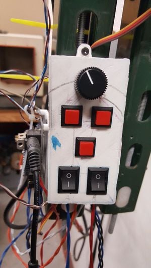
This is a new version of the Recyclebot, which radically reduces the machine shop expenses, but trades up for much faster production.
RECYCLEBOT v4.0ac[edit | edit source]
Source[edit | edit source]
All source files are located on Github. This includes CAD, STL, electronics files and code.
PARTS LIST[edit | edit source]
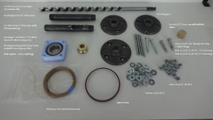
BARREL[edit | edit source]
| Part | Quantity | Additional Details |
|---|---|---|
| Heating tube (½" black pipe) | ||
| Feed tube (½" black pipe) | 6" entry slot cut about 1" from one end of the pipe using an endmill | |
| Floor flange | (x3) | |
| Brass nozzle (½" NPT brass cap) | (hole drilled via lathe, mill, drill press, or hand drill; optimum diameter for the hole is 0.060" drilled with a 1.25mm drill and reamed by pushing a .06 gauge pin through the hole (a 1/16: drill can be substituted with some temperature adjustments | |
| 3" rod, ¼"-20 | (x4) | |
| 1½" bolt, ¼"-20 | (x2) | |
| 2 ¼" bolt, ¼"-20 | (x2) | |
| Nut, ¼"-20 | (x16) | |
| Washer, ¼"-20 | (x64) | |
| Fender washer | (x4) | |
| Kapton tape | ||
| nichrome (nickel chromium) wire | 17 ft | (to be wrapped in continuous coil around heating tube near nozzle end) |
| Bearing – 2" OD, 1" ID with tapered roller bearing race | ||
| Brass spacer (or 'bushing') | turned on a lathe: first OD = 1.25x0.25", second OD = 0.999x0.5"1 ¼" OD, inside = 0.5x0.75" ID, ¾" long | |
| Bearing housing | printed part, plan available from Appropedia |
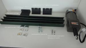
FRAME & MOTOR[edit | edit source]
| Strut channel – 24" long | (x 2) | |
| Barrel bracket – 1 ½" x 2 ¼" x 4" wide angle iron | (x2) | two holes drilled on short edge, two notches cut on long edge |
| Motor mount – 1 ½" x 2 ¼" x 4" wide angle iron | (x2) | two long holes drilled on short edge, two holes drilled on long edge |
| Strut channel T-nut – ¼" D, 20TPI | (x 6) | |
| Socket head bolt – 1" long, ¼" D, 20TPI | (x6) | |
| M6 bolt – 24 mm | (x 2) | comes with motor |
| Split washer – ¼" D, 20TPI | (x 2) | comes with motor |
| Flat washer | (x 2) | |
| Motor – 120-watt gear motor, 15 rpm | (e.g., PC Gear Head Pengcheng Motor) | |
| Coupling – 15 mm keyed coupling with screws | ||
| Deep-well socket – ¼" drive | 5/16" turned down to 15 mm on one surface so, when inserted into coupling, provides flat area for screw to secure it |
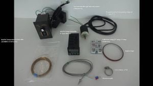
ELECTRICAL COMPONENTS & WIRING[edit | edit source]
| Speed controller – AC current | comes with PC Gear Head Pengcheng Motor | |
| MyPIN Temperature Controller – K-Type SNR | available on Amazon | |
| Solid state relay – 25 amp | 1.2 amp minimum necessary | |
| Kapton tape | ||
| Hose clamp – 1"D | ||
| K-type thermocouple | ||
| Grounded power cord and plug attachment | ||
| Solderless connector (crimp connector) | (x 2) | |
| Insulated copper wire | approximately 10 feet | |
| Terminal strip (or terminal block) | OPTIONAL |
FEEDER ATTACHMENT & HOPPER[edit | edit source]
| Feeder attachment | printed part | |
| Hopper – recycled jug |
FAN[edit | edit source]
| Fan | ||
| Attachment mechanisms | e.g., zip ties |
TOOLS[edit | edit source]
- Knife or wire stripper
- Grease (wheel bearing grease)
- Wrench (x2), socket set, pliers
- Allen wrench for M6 and coupling
- Phillips head for the wiring?
- Hanger
- Connector for feeder?
ABBREVIATIONS USED[edit | edit source]
- ¼"-20 = ¼" diameter, 20 threads per inch
- D = diameter
- OD = outside diameter
- ID = inside diameter
- TPI = threads per inch
PROCEDURE[edit | edit source]
BARREL[edit | edit source]
1. Deepen threads on two of the floor flanges.
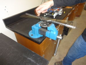
The purpose of this step is to allow the feed tube and heating tube, when screwed into the floor flanges, to extend beyond the base of the floor flanges. (See Photo 1)
- (i.) Using a bench vice, clamp one floor flange with its right side facing upward.
- (ii.) Insert ½" NPT (National Pipe Thread) tap with attached tap handle (if you do not have a tap handle, you can substitute a wrench).
- (iii.) Rotate the tap handle until the tap deepens the threads. The threads need to be made deep enough to allow about 1/8" of tube to extend beyond the floor-flange base when the pipe is screwed into the floor flange (you can determine this by taping the floor flange slightly and, then, checking how far one of the tubes inserts into the floor flange).
- (iv.) Repeat this procedure with the second floor flange.
2. Attach floor flanges with deepened threads to the feed tube and to the heating tube.
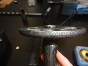
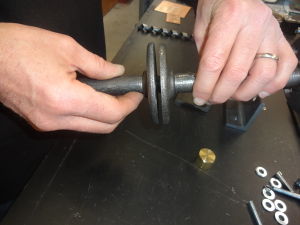
The purpose for this step is to prepare a thermal break to minimize heat transfer between the heating tube and the feed tube. Therefore, the floor-flanged ends of the tubes will not be flush (they will extend beyond) the bottom surface of the floor flanges by 1/8" when you have completed this step; when held base to base, there should be approximately ¼" between the floor flanges. (See Photo 2 and Photo 3)
The feed tube has two distinct ends: the mouth end (end closest to the 'mouth', or feed opening) and the bearing end (end farthest from the mouth that will connect with the bearing block).
- (i.) Screw the mouth end of the feed tube into one deepened-thread floor flange, inserting the tube from the top side.
- (ii.) Make sure that mouth centers between two of the floor-flange bolt holes.
The heating tube will soon have two ends: the feeder end (end closest to the feed tube) and the nozzle end (end that will have heating element and the nozzle). This step will create the feeder end.
- (iii.) Screw one end of the heating tube into one deepened-thread floor flange, inserting the tube from the top side.
3. Attach an unaltered floor flange to the bearing end of the feed tube.
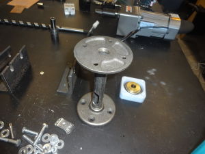
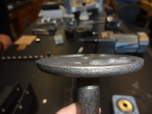
The purpose of this step is to prepare the bearing end of the feed tube for supporting the bearing block; therefore, the end of the tube and the bottom side of the floor flange will be flush.
- (i.) Screw the bearing end of the feed tube into the unaltered floor flange, inserting the tube from the top side
4. Set aside the feed tube.
5. Wrap nichrome wire around heating tube.
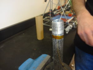
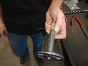
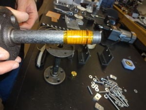
The purpose of this step is to create the heating element—a heating or melting zone within the heating tube. You will create this zone by coiling an insulated wire, nichrome wire, tightly around a small portion of the tube. For this step, the "secure" procedure means wrapping the kapton tape around the outside of the circumference of the tube; you will either need to wrap the kapton tape once around the tube (one wrap) or you will need to wrap the kapton tape around a section of the tube in a spiraling fashion (spiraling-fashion wrap).
- (i.) Measure 17 feet of nichrome wire. While working with the nichrome wire, be careful to avoid kinks in the wire.
- (ii.) Approximate a 4-6" amount of nichrome wire (err on 6" if you are unfamiliar with wiring): this will be the spot on the length of wire that you will secure to the tube. The wire from its free end to this spot (at 4-6") will be an unsecured tail, albeit partly under the wrapped wire.
- (iii.) Hold the wire parallel alongside the tube—free end of the wire directioned toward the feeder end and positioning the identified spot (4-6") of wire about 1/8" or less from the tube threads at the nozzle end.
- (iv.) Secure the wire (at the identified spot) with one wrap of kapton tape onto the side (smooth surface portion) of the heating tube, about 1/8" or less from the threads at the nozzle end. (See Photo 06.)
- (v.) Begin coiling tightly all of the nichrome wire around the heating tube: start the coil as close to the threads as possible while preventing any wire from slipping into the threads.
- (vi.) Coil tightly, leaving no space between each wrap of the coil. You will coil over the kapton tape and part of the tail.
- (vii.) Stop coiling when you have approximately 4-6" remaining, which will form a second unsecured tail; this remainder will be the second unsecured tail. (See Photo 07.)
- (viii.) Secure the end of the coil to the feeding tube with kapton tape.
- (ix.) Proceed to tape the entire wire coil using a spiraling-fashion wrap of kapton tape. (See Photo 08.)
6. Bolt the heating tube and the feed tube together to form the barrel.
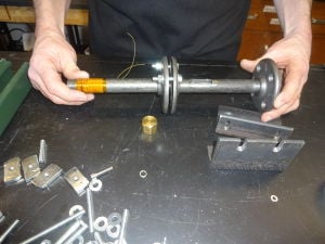
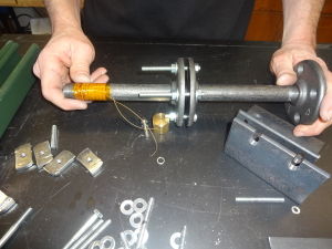
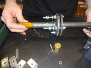
The purpose of this step is to form the barrel of recyclebot. The barrel will have a bearing end, a mouth, a juncture (thermal break), and a nozzle. The mouth of the barrel will be referred to as the front side of recyclebot; the opposite, solid surface will be the back side. The barrel will house the feed screw, which should retain free movement throughout the assembly process until the motor attaches to the feed screw; it is important to continually ascertain and adjust the positioning of all components during this step and the following steps to ensure this free movement.
- (i.) Locate the mouth-end feed tube; this end has the deepened-thread floor flange attached.
- (ii.) Locate the feeder end of the heating tube; this end also has the deepened-thread floor flange attached.
- (iii.) Hold the floor-flange bases of the two located ends together; the pipes should come together completely, but the bases will be separated by a ¼" gap.
- (iv.) Line up the bolt holes of the base-to-base floor flanges.
- (v.) Insert a 1 ½" bolt into a hole on one side of the mouth in this direction: insert from the feed-tube side through to the heating-tube side of the base-to-base floor flanges. Add a washer and then a nut on the heating-tube side. Finger tighten only.
- (vi.) Repeat step of inserting a 1 ½" bolt but inserting it into the free hole on the other side of the mouth. (See Photo 09.)
- (vii.) Prepare two 3" rods: for each rod, screw on a bolt, just a few threads in from one end of the rod (this will be the rod head), and add a washer to each rod via its free end.
- (viii.) Insert a 3" rod into one of the remaining holes that straddle the back side in this direction: insert the free end of the rod from the feed-tube side through to the heating-tube side of the floor flanges. When you complete this step, there should be a bolt and washer on the feed-tube side of the juncture and there should be the free end of the rod on the heating-tube side of the juncture.
- (ix.) Slide a washer and then a nut onto each 3" rod; for each, screw the nut along the rod until it is next to the floor flange. (See Photo 10.)
- (x.) Add two more washers and another bolt to each of the 3" rods; screw these last bolts only part-way along the rods (about 1/8 – ¼"). The spaces between the two bolts on the melting-tube side of the rods will secure the barrel to the frame brackets. (See Photo 11.)
FRAME & BARREL[edit | edit source]
7. Build the frame.
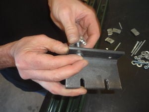
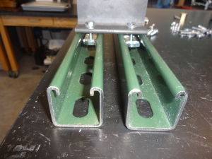
During this step, you will build the frame with brackets (angle-iron brackets) that will support recyclebot's motor, barrel with mouth and nozzle, and fan. (See Photo 12 and Photo 13)
- (i.) Lay the two 24" strut channels parallel to one another (lengthwise) about ¾" apart; open sides should face upwards, holed sides should face downwards, and solid sides should be positioned as sides.
- (ii.) Locate the two pieces of angle iron that two notch cuts on the long side and two holes on the short side. These two pieces will be the brackets for the barrel; these will be called the barrel brackets (the remaining angle-iron with four drill holes will be the motor bracket).
- (iii.) Insert a 1" bolt into one of the holes on one barrel bracket in this manner: from the inside face through to the outside face (back side); slide a washer and a t-nut onto the 1" bolt. Repeat this process with the second hole.
- (iv.) Repeat the step, 7 iii, of inserting screws, washer, and t-nuts.
- (v.) Set the short edge of one barrel bracket on the strut channel by dropping one T-nut into each piece of strut channel; in other words, the short edge of the barrel bracket should straddle the parallel pieces of strut channel. Slide this barrel bracket along the strut channel in the direction that the short edge is pointing until the barrel bracket is 7" from one end. This barrel bracket will be closest to the nozzle, which is the bottom of recyclebot, and will accommodate the fan.
- (vi.) Set the short edge of the second barrel bracket, pointing the short edge away from the nozzle-end barrel bracket, by dropping one T-nut into each piece of strut channel; the short edge of the barrel bracket should also straddle the parallel pieces of strut channel. The long edges of both barrel brackets should face towards each other. Slide this second piece along the frame until it is about 6-7" away from the nozzle-end barrel bracket. This will be closest to the bearing end.
8. Arrange the barrel on the frame.
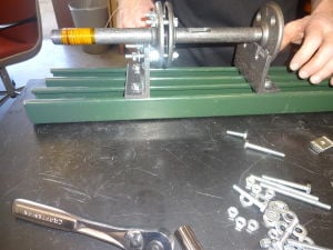
To perform this procedure, you will need to slide the barrel brackets to align with the barrel. The mouth of the barrel should face upwards. (See Photo 14 and Photo 15)
- (i.) Hold the barrel directly above the frame in a parallel manner so that the both barrel and frame nozzle ends align and both barrel and frame bearing ends align.
- (ii.) Align the 3" rods of the juncture over the notches of the nozzle-end barrel bracket (from 7v); when lowered, you will want the bracket notch to have one washer and one nut on each side (from 6x).
- (iii.) Slide the bearing-end barrel bracket (from 7vi) so that it will support the barrel immediately next to the bearing-end floor flange.
- (iv.) Hold the while holding the juncture of the barrel over the nozzle-end barrel bracket, position the bearing end of the barrel over the second barrel bracket (from 7vi).
- (v.) Lower the barrel so that the rods rest in the notches of the barrel brackets while ensuring that one washer and one nut on each juncture rod remains on each side of the bracket notch.
9. Add rods to secure bearing-end floor flange of the barrel to secure it to the bearing-end bracket notch.
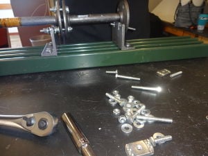
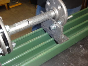
Now, the juncture should be completely supported by the rods in the bracket notches. The bearing-end of the barrel should be resting on one bracket between two notches; two floor-flange holes should align with two of the bracket notches. The mouth should be facing upwards. (See Photo 15 and Photo 16)
- (i.) Add one nut to a 3" rod, and screw the nut along the rod to about 1" in from the end. Repeat this with a second 3" rod.
- (ii.) Slide a washer on the 2" side of the rod. Repeat this for the second 3" rod.
- (iii.) Locate the holes of the bearing-end floor flange that align with the bearing-end bracket notches.
- (iv.) Insert each 3" rod into one of the two aligning holes (from 8ii) as follows: while lifting the barrel slightly, insert the long portion of the rod from the inside of the floor flange toward the outside until the washer and nut come to rest on the floor flange. The remaining 1" portion of the rod will rest in the bracket notch. The 2" portion of the rod will be protruding out the bearing end.
- (v.) Add one washer to each of the rods on the 1" side, lifting the barrel as necessary so that these washers are next to the nuts. When finished with this step, you should have a washer, a nut, and a washer on the short portion of the rod between the floor flange and the bearing-end bracket notch.
- (vi.) Add one washer and one nut to the short ends of each rod on the opposite side of the bracket notch (not between the floor flange and the bracket).
10. Tighten bolts on juncture barrel bracket.
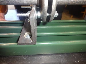
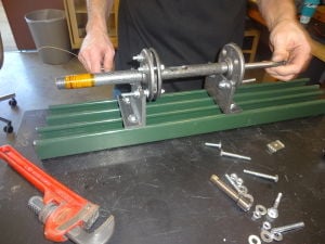
Before beginning this step, the barrel brackets should be completely supporting the barrel via four 3" rods in the four bracket cuts. The tube may be in contact with the bracket; this is acceptable. The brackets should still be unsecured on the frame; you will tighten this after the motor has been added. Throughout this step, you should constantly be checking for free movement of the feed screw inside the barrel. This is mentioned in the steps below as a reminder to check for its free movement. Keep in mind: you may need to loosen these bolts during step 22 to ensure the entire barrel-and-feed-screw unit are in horizontal alignment with the motor shaft. (See Photo 17 and Photo 18)
- (i.) Insert the feed screw into the tube.
- (ii.) Tighten bolts on either side of the bracket for both of the rods at the juncture. You will need to use a socket set and wrench or use two wrenches; one wrench will grasp the nut between the floor flange and the bracket while the other wrench or socket set will tighten the nut on the other side of the bracket notch.
11. Tighten bolts of the juncture between feed tube and heating tube.
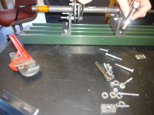
Before beginning this step, the barrel brackets should still be freely moveable on the frame. (See Photo 19)
- (i.) Finger tighten nuts that join the floor flanges in a diagonal pattern: one bottom nut on rod underneath the mouth, top bolt and nut on the opposite/diagonal side, top bolt and nut on the other side, remaining bottom nut on rod underneath the mouth. Ensure the feed screw moves freely inside the barrel; if it does not, adjust as necessary.
- (ii.) Tighten the bolts using a wrench and a socket set or using two wrenches (alternatively, pliers work as well); use the wrench (or pliers) to grasp the spacer nuts while tightening the outside nuts with socket set, wrench or pliers. Ensure the feed screw moves freely inside the barrel; if it does not, adjust as necessary.
12. Tighten bolts on bearing-end barrel bracket. Keep in mind: you may need to loosen these bolts during step 22 to ensure the entire barrel-and-feed-screw unit are in horizontal alignment with the motor shaft. (See Photo 18)
- (i.) Using a wrench to grasp the spacer nut and either a wrench of socket set to grasp the interior nut, tighten the nuts on either side of the bearing-end barrel bracket. Insert the feed screw continues to move and rotate freely in the barrel.
13. Insert the feed screw. Add the brass spacer, the tapered roller bearing, and the race to the hex-stock end of the feed screw.
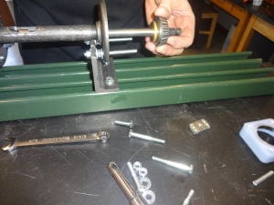
Before you begin this step, the barrel of recyclebot should be completely tightened onto the frame. The feed screw, when inserted into the barrel should freely move and should spin when rotated. The brass spacer used in this step is made by turning it on a lathe; this can be made at a local machinist shop. (See Photo 20)
- (i.) Insert the feed screw completely into the barrel ensuring that the feed screw can freely move and rotate. You should insert it by grasping the hexagonal end of the screw—called the hex stock or hex key—and inserting the spiral end into the barrel. A small amount of smooth-sided feed screw and the hex stock and should be exposed at the bearing end of the barrel.
- (ii.) Grease the tapered roller bearing (alternatively, you may grease it immediately before a final tightening of all components). Every surface of the roller bearing should be thoroughly greased—you must force grease into all of the rolling elements of the tapered roller bearing while avoiding air bubbles in the grease. For a demonstration, you may find video tutorials on 'how to grease a roller bearing' online.
- (iii.) Fit the narrow end of the brass spacer into the wider end of the bearing and race.
- (iv.) Slide the spacer, bearing, and race onto the exposed portion of the feed screw—spacer side first and race side last.
14. Slide the bearing housing onto the feed screw; bolt bearing housing to bearing-end floor flange of the barrel.
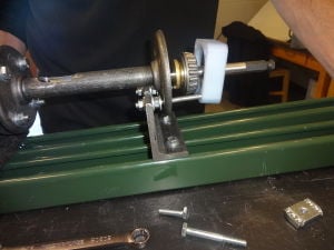
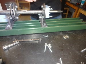
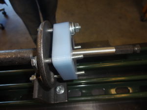
(See Photo 21, Photo 22, and Photo 23)
- (i.) Add one washer to the open-end (2" portion) of the rods at the bearing end.
- (ii.) Insert a 1 ½" bolt into the open upper hole on the floor flange, from barrel side to bearing side. Repeat this with another 1 ½" bolt and the second open upper hole.
- (iii.) Add one washer to each of the bolts (from 14ii).
- (iv.) Slide the bearing housing onto the feed screw. Notice the four holes—bolt holes—on the bearing housing printed part: As you cover the race, bearing, and spacer with the bearing housing, slide the bearing housing bolt holes onto the 3" rods and the 1 ½" bolts.
- (v.) Add one fender washer to each rod. Add one nut to each rod. Using a wrench, tighten the nuts.
This unit—the brass spacer, roller bearing, race, and bearing housing—will be referred to as the bearing block.
15. Attach the brass nozzle.
- (i.) Screw the brass nozzle onto the heating-element end of the barrel.
FAN[edit | edit source]
16. Attach fan under the juncture barrel bracket.
- (i.) Attach the fan under the juncture barrel; this fan must extend to just below the nozzle in order to blow on the filament and cool the filament as it is being produced.
MOTOR[edit | edit source]
17. Prepare the motor mount and attach it to the strut channel frame.
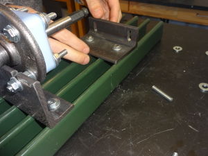
The third angle-iron bracket with four drill holes (cut on both short and long edges) is the motor mount. While the barrel brackets affix to the frame via short edges, the motor mount affixes to the frame via long edge, allowing the short edge to jut out from the frame and act like a self for the motor. (See Photo 24 and Photo 25)
- (i.) Insert a 1" bolt into each hole on the long edge in this fashion: from the inside face through to the outside.
- (ii.) Add a washer and a T-nut to the end of each bolt.
- (iii.) Position the motor mount over the frame between the bearing-block region and the end of the frame.
- (iv.) Hold the motor with T-nuts are hanging down from the bracket, short edge pointing upwards, and short edge facing the end of the frame.
- (v.) Lower the motor mount so T-nuts drop into the strut channel frame (one into each bar of the strut channel frame; similar in procedure to 7v and 7vi).
18. Tighten bolts with t-nuts on strut channel frame.
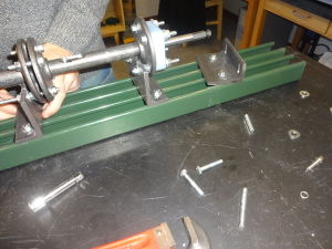
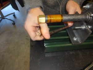
(See Photo 26 and Photo 27)
- (i.) Slide the barrel brackets as necessary so that the juncture barrel bracket is about 7" from the end of the frame; this will allow the nozzle to extend beyond the end of the frame.
- (ii.) Tighten both bolts on the short edge of the bracket, which have T-nuts on the reverse side and which are in direct contact with both parallel pieces of strut channel, using a socket set or a wrench.
- (iii.) Tighten bolts on bearing-end bracket.
19. Insert the socket into the coupling. Attach socket and coupling to the motor shaft. The deep-well socket is a standard 5/16" socket that has been turned down on one side using an end-mill. This is to create a flat surface to secure it via screws to the coupling. This unit will function as an adapter between the motor's shaft and the feed screw.
- (i.) Insert the socket into the coupling with the flat surface positioned towards the screws/screw holes on the top side of the coupling.
- (ii.) Insert a set screw into each hole and tighten screws down, with an Allen wrench, to the flat surface of the socket.
20. Affix coupling-socket unit to the shaft of the motor.
- (i.) Slide coupling-socket unit onto the motor shaft, coupling side first (the socket will accommodate the feed screw).
21. Position motor to determine where you will need the motor mount. Tighten the motor mount to the frame.
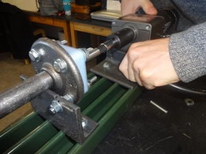
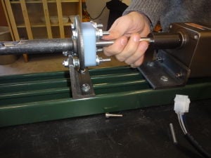
The purpose of determining where the feed screw "bottoms out" is to allow the feed screw to press back against the bearing, which should assume the pressure rather than the motor. (See Photo 28 and Photo 29)
- (i.) Pull back on the feed screw until it bottoms out at the bearing (about 1/8"). This is the position of where the feed screw should securely attach to the motor.
- (ii.) Tighten the motor mount to the frame using wrench or socket set.
22. Position the motor on the frame and attach the motor to the motor mount.
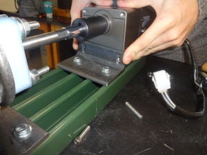
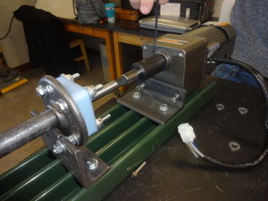
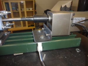
(See Photo 30, Photo 31, and Photo 32)
- (i.) Prepare two M6 bolts by, first, adding a split washer and, then, adding a flat washer second to each bolt.
- (ii.) Lay the motor face up against the outside-surface, short-edge of the motor mount.
- (iii.) Notice the two holes on the motor mount that correspond with the two back holes on the motor; align these holes.
- (iv.) Screw the motor to the mount by inserting the prepared M6 bolt (from 22i) from the inside-surface, short-edge of the motor mount, through the motor mount, and into the back two hole of the motor.
At this point, you need to verify that everything is in exact alignment on a horizontal plane: motor shaft, feed screw, and barrel. If it is not, you may need to loosen the bolts on the barrel brackets (from steps 10 and 12) and either raise or lower the entire barrel slightly. Your goal is to ensure completely free movement of the feed screw.
This is also the alternate time to grease the bearing—you will need to remove it from the bearing housing and then replace the unit.
WIRING[edit | edit source]
Before beginning the wiring, keep in mind that black and white wires are power wires and the green wire is the ground wire. You will need approximately 10 feet of insulated copper wire. For each connection, measure the appropriate amount for your desired set up (that is, for the distances determined by where you want your final placements of each component of recyclebot). When stripping wires, you do not want to strip them back any more than ¼" so that the stripped portion of the wire will not extend beyond the connection pads.
You have two options for wiring. You may either use point-to-point wiring or you may use a terminal strip (or terminal block). The pictorial wiring schematic illustrates how the components must connect and you may choose your preferred method for achieving these connections.
23. Connect the motor cord to the speed controller with the Molex. If necessary, adjust speed controller for direction.
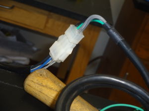
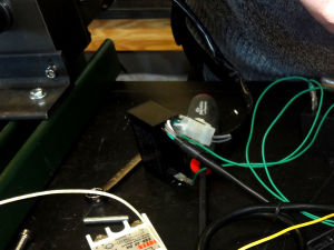
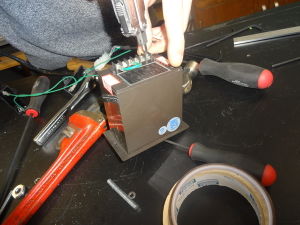
(See Photo 33, Photo 34, and Photo 35)
- (i.) Attach the Molex (plastic connector of the motor cord) to the plastic connector on the speed controller (the speed controller comes packaged with the motor). This is the AC current line.
- (ii.) Determine the direction that you want your feed screw to operate: a small green wire affixed to the back to the speed controller should loop from the COM slot to the CCW (counterclockwise) pin, which is the standard operating direction. You may need to move the loop to achieve from COM slot to the CW (clockwise) pin if you need to reverse recyclebot (e.g., in case it becomes bound up).
24. Attach the hose clamp to the brass nozzle.
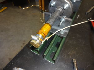
(See Photo 36)
- (i.) Loop the hose clamp around the brass nozzle.
- (ii.) Strip the ends of the Type K thermocouple wire about ¼". Wrap these ends in kapton tape.
- (iii.) Insert these end into the space between the hose clamp and the brass nozzle (be sure the bulk of the wire exits towards the barrel and not in the direction of the nozzle).
- (iv.) Tighten the clamp.
25. Crimp the nichrome wire tails of the heating element to insulated copper wire.
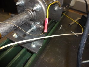
For this step, you will be preparing a length of wire that will connect the nichrome heating element to the solid state relay. (See Photo 37)
- (i.) Insert one tail of the nichrome wire into one end of a crimp connector (solderless connector); insert one end of insulated copper wire into the other end of the crimp connector. These wires should be inserted far enough into the tube so that they will be overlapping.
- (ii.) Crimp the wire by crushing the crimp connector's center, encasing the wire.
- (iii.) Repeat this crimping process with the second tail of nichrome wire and a second piece of insulated copper wire.
26. Refer to the wiring schematic to make the appropriate connections.
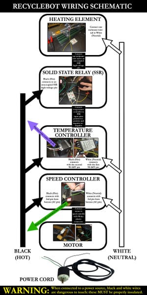
(See Wiring Schematic) For all connections, the appropriate procedure is
- (i.) Loosen the pin, insert stripped end of wire, and tighten the pin.
27. Check the electrical current resistance using a voltmeter.
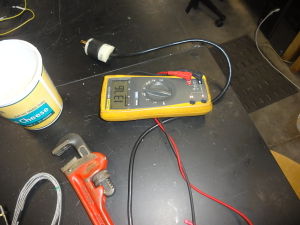
As you completes the wiring of recyclebot, you must check your connections with a voltmeter. The voltmeter should register above 125 ohm); if the resistance of the coil is too low, you will risk a fire at the heating element of recyclebot. (See Photo 38)
- (i.) Locate both ends of copper wire connected to nichrome tails of the heating element.
- (ii.) Detach the copper wire from the pins to which they are connected.
- (iii.) Make contact with one wire end and one voltmeter prong.
- (iv.) Make contact with the remaining wire end and the other voltmeter prong.
- (v.) Ensure that the resistance is above 125.
28. Connect to a power source and turn on recyclebot.
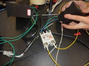
You may now connect recyclebot to a power source. (See Photo 39) As the heating element is warming up, pay attention to the temperature that is being registered by the temperature controller. If the temperature drops rather than rises, you will need to disconnect recyclebot from the power supply and switch the nichrome-attached copper wire connections (simply swap one connection for the other).
HOPPER[edit | edit source]
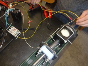
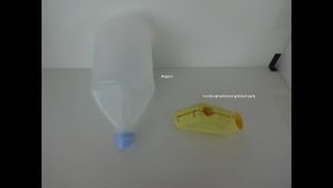
Affix the feeder attachment via hopper to the mouth of recyclebot. The photo depicts a horizontal operating recyclebot that uses an upright printed-part box feeder that attaches with plastic box ties. The parts diagram illustrates an attachment for a vertically-hanging recyclebot: a large-capacity feeder constructed out of a recycled plastic jug (eg. vinegar jug) and a printed-part hopper. (See Photo 40)
Fill the feeder with PLA or recycled plastic pieces. The motor will be turning. When the heating element begins to melt the plastic into filament, the PLA or plastic pieces will proceed through the mouth opening and down the barrel.
Electronics[edit | edit source]
See Github
Operation of Use[edit | edit source]
Control Panel[edit | edit source]
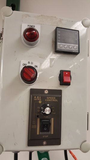
Make sure everything is off before turning the control panel on. The recycle bot will not turn on if any of the switches are on.
- Flip the red, circle switch on. You should see the temperature display screen turn on. The machine will start heating up to the temperature on the screen.
- Allow the machine to heat up to the assigned temperature before turning the hopper on.
- Once temperature is reached, turn the hopper on by pressing red switch under the speed dial. If the machine squeaks, turn the hopper off and wait until the recyclebot gets warmer.
Motor[edit | edit source]
- Make sure the circuit board is plugged into a power supply.
- Turn on the right switch on the white box on the side of the recyclebot. The circuit board should have a green glow.
- Press the top two red buttons together. The motor should turn on, and the machine should start spinning so you can spool the filament.
