
The Sexual and Reproductive Health and Rights (STARS) - Cervical Cancer Screening and Treatment module's Thermocoagulator Simulator allows nurses, midwives, clinical officers, and medical officers to become confident and competent in performing thermal ablation of cervical pre-cancer lesions as part of cervical cancer screening and treatment procedures performed in primary health care facilities and mobile units in resource-constrained settings. The Thermocoagulator Simulator is modelled on the Liger Medical HTU-110 Thermocoagulator™ and contains 5 componentsː (1) probe shaft with heating tip (including hot and cold probes of different probe tip diameters), (2) smartphone light to visualize the cervix, (3) mobile app-based user interface, (4) handle, and (5) augmented feedback circuit to alert the user if the heated probe touches the vaginal sidewalls of the Gynecologic Simulator.
Thermocoagulator Simulator[edit | edit source]
This section explains how to construct the handle and "hot" and "cold" probe shafts with heating tips of the Thermocoagulator Simulator. The Liger Medical HTU-110 Thermocoagulator™ is designed with a probe shaft with heating tip that is inserted and removed unheated ("cold") which can reduce the risk of burn injury to the patient.[1] Other commercially available thermocoagulators are designed with probe shafts and heating tips that are inserted and removed while heated ("hot") which potentially increases the risk of thermal injury to the patient and practitioner. The Thermocoagulator Simulator is designed with removeable probes so the learner can practice thermal ablation with hot and cold probes.
Materials[edit | edit source]
- Corrugated Cardboard
- Scissors (sturdy enough to cut cardboard)
- Pencil
- Ruler
- 2 Elastic Bands
- 2 Toothpicks
- Aluminum Foil
- Tape
- Android Mobile Phone with Thermocoagulator Simulator App
Assembly Instructions[edit | edit source]
Base[edit | edit source]

Cut out base (rectangle with three tabs) as shown.

Measure and cut a 4.0 cm slot that lines up with the tab on the far right.

Roll the cardboard into a cylinder and insert the tab into the slot.

Secure base with tape.
Body[edit | edit source]

Cut out body as shown.

Create three 1.0 cm diameter holes and one horizonal slot in the center of the body as shown.

Use toothpick to make two pairs of small holes in the body on the shaded section.

Loop one elastic in each pair of small holes from the back of the body (the left side of each step is facing the viewer).

Use a ruler to make straight folds in the body at the 4 measured sections (shown as 4 black horizontal lines).

- Fold body to form an uppercase M-shape. TIP: The three 1.0 cm diameter holes should line up together.
- Insert the tab into the slot.

On the section of the body with no holes, line up the base in the center and mark its general position as shown.

Remove the tab from the slot and cut out the two curved marks.

- Insert the base into the cut out marks on the body.
- Re-insert the tab into the slot.

Tape the folded and layered cardboard sections together.
Probe Shaft[edit | edit source]

Cut a 3.0 cm by 23.0 cm rectangle out of cardboard as shown.

Roll the rectangle into a 1.0 cm diameter, 23.0 cm long cylinder as shown.

- Secure with tape along the 1.0 diameter shaft as shown.
- Repeat Steps 1-3 three times to make a total of 4 probe shafts.
16.0 mm Diameter Cold Probe Flat Tip[edit | edit source]

Cut the cardboard in the shape as shown. The 5.0 cm length of the taller rectangle is the circumference for the 16.0 mm diameter probe tip.

Tape the thinner end of the cardboard strip firmly to the probe shaft.

- Wrap the strip around the probe shaft while taping along the way.
- Place tape perpendicular to the probe tip to secure it in place.

Once the taller portion of the cardboard strip is reached, place and fold a long piece of tape over the top of the probe tip. IMPORTANT: This prevents the probe tip from sticking to the clay cervix model.

- Line up and tape together the edges of the taller 5.0 cm long rectangle of the probe tip to create a circular probe tip with an outer diameter of 16.0 mm.
- Continue wrapping and securing the probe tip to the probe shaft using tape.

Use a ruler to check that the probe tip's outer diameter is 16.0 mm.
19.0 mm Diameter Cold Probe Flat Tip[edit | edit source]

Cut the cardboard in the shape as shown. The 6.0 cm length of the taller rectangle is the circumference for the 19.0 mm diameter probe tip.
Tape the thinner end of the cardboard strip firmly to the probe shaft.
- Wrap the strip around the probe shaft while taping along the way.
- Place tape perpendicular to the probe tip to secure it in place.
Once the taller portion of the cardboard strip is reached, place and fold a long piece of tape over the top of the probe tip. IMPORTANT: This prevents the probe tip from sticking to the clay cervix model.
- Line up and tape together the edges of the taller 6.0 cm long rectangle of the probe tip to create a circular probe tip with an outer diameter of 19.0 mm.
- Continue wrapping and securing the probe tip to the probe shaft using tape.

Use a ruler to check that the probe tip's outer diameter is 19.0 mm.
Cold Probe Augmented Feedback Feature[edit | edit source]

For each cold probe, cut a 7.0 cm by 30.0 cm rectangle out of aluminum foil.

- Line up the edge of the aluminum foil to the edge of each cold probe tip.
- Tape the aluminum foil to the cold probe tip. IMPORTANT: Do not cover the flat (top) surface of the cold probe tip with aluminum foil.
- Make a loop with the tape so that one side of the tape will stick to the aluminum foil and the other side of the tape will stick to the probe tip. IMPORTANTː Do not cover the aluminum foil with tape on the outside of the probe as this will insulate the electrical circuit so it will not work properly.

Secure the loose aluminum foil on the probe tip.

Wrap the remaining aluminum foil around the probe shaft, leaving approximately 3.0 cm uncovered (foil-free) at the end of the probe shaft that will be inserted into the body of the Thermocoagulator Simulator.

When finished, the cold probe tips should appear as shown.
19.0 mm Diameter Hot Probe Flat Tip[edit | edit source]

Cut the cardboard in the shape as shown. The 6.0 cm length of the taller rectangle is the circumference for the 19.0 mm diameter probe tip.
Tape the thinner end of the cardboard strip firmly to the probe shaft.
Wrap the strip around the probe shaft while taping along the way.
- Line up and tape together the edges of the taller 6.0 cm long rectangle of the probe tip to create a circular probe tip with an outer diameter of 19.0 mm.
- Continue wrapping and securing the probe tip to the probe shaft using tape.
- Use a ruler to check that the probe tip's outer diameter is 19.0 mm.
Use a ruler to check that the probe tip's outer diameter is 19.0 mm.
25.0 mm Diameter Hot Probe Flat Tip[edit | edit source]

Cut the cardboard in the shape as shown. The 8.0 cm length of the taller rectangle is the circumference for the 25.0 mm diameter probe tip.
Tape the thinner end of the cardboard strip firmly to the probe shaft.
Wrap the strip around the probe shaft while taping along the way.
- Line up and tape together the edges of the taller 8.0 cm long rectangle of the probe tip to create a circular probe tip with an outer diameter of 25.0 mm.
- Continue wrapping and securing the probe tip to the probe shaft using tape.

Use a ruler to check that the probe tip's outer diameter is 25.0 mm.
Hot Probe Augmented Feedback Feature[edit | edit source]

For each hot probe, cut a 9.0 cm by 30.0 cm rectangle out of aluminum foil.

Place the probe tip and shaft around 5.0 cm down from the edge of the foil.

Wrap the foil gently over the tip while pressing down on the probe tip outline. The probe tip outline should project slightly from the rest of the aluminum-foil covered probe tip to leave an impression of the treated area on the clay cervix model.

Wrap the remaining aluminum foil around the probe shaft, leaving approximately 3.0 cm uncovered (foil-free) at the end of the probe shaft that will be inserted into the body of the Thermocoagulator Simulator.
When finished, the hot probe tips should appear as shown.
Use with Phone[edit | edit source]

Measure and mark 5.0 cm from the bottom edge of the Thermocoagulator Simulator (as shown).

- Place the cellphone in the center of the Thermocoagulator Simulator as shown.
- Position a toothpick next to the cellphone at the 5.0 cm mark.

- Use the toothpick to puncture through the body at a 45 degree angle to come out next to then base.
- Repeat Steps #2 and #3 for the second toothpick on the opposite side of the cellphone.

Slide the cellphone into the elastics, starting with the lower elastic.

Wrap the bottom elastic around the toothpicks until the cellphone is tightly secured in place.

Insert the desired probe shaft into the 1.0 cm hole in the front of the Thermocoagulator Simulator which is almost ready for use!
Augmented Feedback Feature[edit | edit source]
This section explains how to construct the augmented feedback feature of the Thermocoagulator Simulator. The purpose of this targeted feedback is to alert the learner if the thermocoagulator probe shaft, which has a maximum temperature of 43 degrees Celsius, comes into contact with the inner vagina, and thereby, exposes the patient to a potential thermal injury.
Materials[edit | edit source]

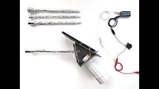
You will need the following materials:
- Optionalː Wire Stripper
- Alligator Clips (minimum 4)
- Buzzer
- 9 V Battery
- Non-Insulated, Small Gauge Wire
- Scissors
- Tape
- Ruler
Not shown in imageː
Assembly Instructions[edit | edit source]

- Form a loop of the exposed wire of the black insulated end of the buzzer. TIP: Use the optional wire stripper to remove the colored plastic insulation covering the wire.
- Clip an alligator clip on the exposed wire loop of the black insulated end of the buzzer. TIP: Clip the alligator clip perpendicular to the longitudinal axis of the exposed wire loop.
- Connect the alligator clip from the exposed wire on the black insulated end of the buzzer to the negative lead of a 9 V battery.

- Attach a second alligator clip to the exposed wire of the red insulated end of the buzzer to the positive lead of the 9V battery.
- If the buzzer makes a sound, then the alligator clips are connected to the proper battery lead.
- If the buzzer does not make a sound, then switch the alligator clips to the opposite battery leads. The buzzer should now make a sound. If the buzzer still does not make a sound, try using a new battery or a different buzzer.
- Disconnect the second alligator clip (which is attached to the exposed wire of the red insulated end of the buzzer) from the lead of the 9V battery.

Connect the second alligator clip (attached to exposed wire of the red insulated end of the buzzer) to the exposed (non-taped) aluminum foil of the Vaginal Canal of the Gynecologic Simulator.

- Cut a small length of small gauge wire.
- Loop and twist together the two ends of the small gauge wire around the aluminum foil covering the proximal probe shaft of the Thermocoagulator Simulator.
- Attach one alligator clip to the wire loop around the proximal probe shaft.
- Wind this alligator clip down the front of the Thermocoagulator Simulator and around the handle of the Thermocoagulator Simulator.
- Tape a section of the alligator clip that winds around the handle of the Thermocoagulator Simulator.
- Attach a second alligator clip to the free end of the alligator clip attached to the wire loop around the proximal probe shaft.

- Connect the alligator clip from the Thermocoagulator Simulator to the other (unused) lead of a 9 V battery.
- IMPORTANT: Please put on gloves to prevent you from directly touching any material which can conduct a live electrical circuit.
- Test the augmented feedback circuit by placing the Thermocoagulator Simulator probe tip on the aluminum foil simulating the vaginal sidewall of the Gynecologic Simulator. The buzzer should now make a soundǃ
Thermocoagulator Simulator Mobile App[edit | edit source]

The innovative Thermocoagulator Simulator Mobile App, was programmed in MIT App Inventor by Jude Barnabas, an Ugandan Medical Maker, and is designed to simulate the Liger Medical HTU-110 Thermocoagulator™ user interface, light illumination feature, and sounds heard during thermal ablation. This mobile app also directs the user to use the cellphone camera to take pre- and post-treatment photos of the cervix for the self-assessment framework.
Equipment[edit | edit source]
- Android Smartphone
- Internet Connection
Android App Installation Instructions[edit | edit source]
- Open the Google Play Store application.
- Type in "Thermocoagulator Simulator" in the search bar at the top.
- Select the Thermocoagulator Simulator app which displays the Medical Makers logo as the app icon.
- Press on Install to install the Thermocoagulator Simulator app.
- When ready, press on the Thermocoagulator Simulator app icon to open the app.
Noteː In the next phase, we will be developing an additional feature of the Thermocoagulator Simulator Mobile App to simulate the user interface for a thermocoagulator device with a hot probe. For now, the same user interface in the Thermocoagulator Simulator Mobile App will be used for skills training for both cold and hot probes.
References[edit | edit source]
Sections of the STARS - Cervical Cancer Screening and Treatment module are copied or adapted from: Training of health staff in VIA, HPV detection test and cryotherapy - Facilitators' guide. New Delhi: World Health Organization, Regional Office for South-East Asia; 2017. Licence: CC-BY-NC-SA-3.0 IGO; and WHO guidelines for the use of thermal ablation for cervical pre-cancer lesions. Geneva: World Health Organization; 2019. Licence: CC-BY-NC-SA-3.0 IGO. The World Health Organization (WHO) is not responsible for the content or accuracy of any translation. The original English edition shall be the binding and authentic edition.
- ↑ HTU-IFU-002 TC Thermocoagulator Instructions for Use Rev B 04/2021 CN 0354 [product insert]. Liger Medical; 2021.