Tensile test protocol: MOST
This page describes the protocol to be followed when performing tensile testing for the MOST Research Group at Michigan Technological University. While this protocol contains some information applicable to all tensile testing, it is designed specifically for testing with the mechanical testing facilities in the Materials Science and Engineering Department.
Testing Protocol[edit | edit source]
Test specimen: http://www.thingiverse.com/thing:28987
Test Facilities[edit | edit source]

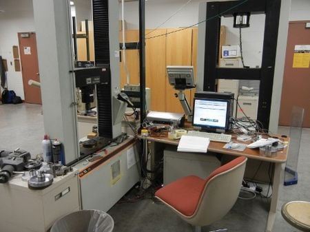
Mechanical testing is performed in room 413 of the Minerals and Materials Engineering Building (M&M). A variety of test equipment is available for tensile, compression, fatigue, and bending.
Before you perform any tests for the first time, have a MOST member familiar with the equipment and procedure demonstrate a test for you or contact Paul Fraley (M&M 522, pdfraley@mtu.edu) for help.
For tensile testing, the Instron testing system located in the middle of the room is to be used. This system is connected to and controlled by the computer located next to it.
Set Up[edit | edit source]

How the equipment is set up is determined by the test to be performed and the material to be tested. The set up described here is for testing polymer samples in tension from 3-D printing.
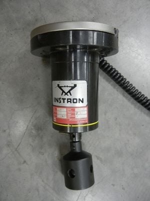
The force applied to the specimen is measured with a load cells. Multiple load cells are available differing by the maximum load they measure. The load limit of the load cell should be close to the expected load to be applied to the specimen. Because polymers will fail at smaller loads than metals, a smaller load cell should be used. In this case, the smallest load cell available in the lab with a load rating of 10kN is to be used.
If a different load cell is attached to the test system, it will have to be removed and the small load cell put on. This is done by removing the allen-head bolts holding the load cell to the underside of the crosshead. The smaller load cell will have a different bolt pattern than the larger one, so it will use different bolt holes in the crosshead when you mount it. Make sure that all bolts are well tightened.
Computer Settings[edit | edit source]
The software used to extract data from the tensile tests is the TestWorks 4.
Before performing any test, it is important to choose the method and calibrate the load cell and the extensometer!
Choosing the method[edit | edit source]
When you open the software the first thing you do is to choose the method, which basically tells the program the information required to perform the test. The MOST standard test for 3-D printed dogbones is:
Data Acquisition rate = 10.0 Hz
Extensometer Gage Length = 50 mm
Test Speed = 5.00 mm/min
Load cell calibration[edit | edit source]

To calibrate the load cell:
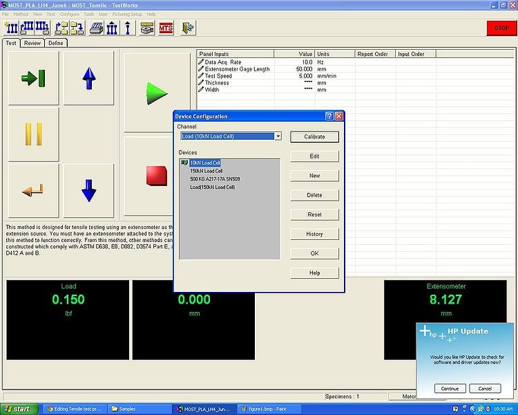
- Go "Configure ->Device". The "Device Configuration" window is going to open.
- Choose the channel related to Loads and it will give you all devices settings available.
- Choose the one which matches with the load cell in use (10 kN, for example) and click "Calibrate" (see screenshot).
- A new window is going to open showing a message telling that the device calibration was set to none. Click "OK" to end the load cell calibration.
Extensometer calibration[edit | edit source]

- Go to "Configure ->Device" again, but this time select a channel related to the extensometer, select the kind of extensometer, which is related to the value of the Gage length (50 mm, for example), in use.
- Click "Calibrate" (Figure).
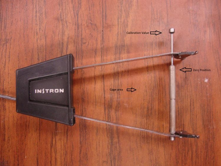
- Once the Calibration window opens, it will ask to set the device to zero. In order to to that make the hinge knife touch the measuring transducer (Figure), i.e. the zero position, and click "next". So enter the calibration value which is the maximum distance the hinge knife can do (Figure).
- Finally, set the device to the calibration value (Figure) and press "Finish".
Performing the Test[edit | edit source]
- To perform a test, first the width and thickness have to be measure on three different spots of the specimen, one in the middle and the other two near the heads. The average of the measurements is taken and used as input on TestWorks. Once the measurements are done, calibrate the load cell and the extensometer as specified above.
- The specimen can be fixed on the tensile machine by adjusting the grips. The software also enables the user to adjust the distance between the grips so the specimen can fit correctly. Make sure the grips are distant enough so the extensometer can be used.
- To fix the extensometer, position it on the Gage area and attach it by using rubber bands on both knifes ends.
- Having everything set, click the "Run the test" button.
- The "Required inputs" window is going to open asking for the values for the thickness and width. Type them and press OK to run the test.
- When the break is detected, the test stops and the graphic of Load x Extensometer is generated and properties as the Young's ModulusW, Peak LoadW, Peak StressW and others are computed on the Review tab.
- It is possible to edit commentaries about the test by clicking with the right button the specimen test on the left side of the window(named as 1, 2, 3...) and choosing "Edit Comment".
- You can organize the specimens in groups of samples by creating new samples on the "File" tab which can be really helpful when different kinds of materials are been tested.
Remember: Take careful notes on your samples and the tests in your lab notebook. Make a backup of the results.
Applications[edit | edit source]
See: Mechanical testing of polymer components made with the RepRap 3-D printer
- Mechanical Properties of Components Fabricated with Open-Source 3-D Printers Under Realistic Environmental Conditions
- The Effects of PLA Color on Material Properties of 3-D Printed Components
- Viability of Distributed Manufacturing of Bicycle Components with 3-D Printing: CEN Standardized Polylactic Acid Pedal Testing
- Tensile Strength of Commercial Polymer Materials for Fused Filament Fabrication 3-D Printing

