Laser surface texturing

Laser surface texturing (LST) is a surface engineering process used to improve tribologicalW characteristics of materials. Using a laserW to create patterned microstructuresW on the surface of the materials can improve load capacity, wear rates, lubrication lifetime, and reduce friction coefficients. The use of surface irregularities to improve tribological properties was first discussed in the 1960's and is implemented in several manufacturing techniques.[1] While surface texture engineering has been studied for many years, the use of laser patterned surface microstructures for tribological improvements emerged in the 1990's and continues to undergo significant technological advancements. Lasers offer unparallel control of the surface microstructure and a low environmental impact compared to other surface etching processes.[2] Given that frictionW creates unavoidable losses and wear in countless processes and devices, the opportunities for improving efficiency and lifespan with LST technologies are extensive. As well, LST offers possibilities to overcome stictionW, for example in microelectromechanical systemsW.[3]
Basic Underlying Principles[edit | edit source]
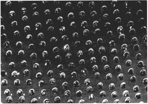
LST is a materials process used to create patterned microstructures on the contact surface of the work piece. While different patterns can be used, the common microstructures are linear grooves, crossed grooves, and circular dimple-like depressions (Figure 1). These microstructures function to improve tribological characteristics in several manners. The effects listed below act in different magnitudes dependant on several application-specific properties (lubricant viscosityW, micropore geometry, relative contact velocity, load pressure, etc.).[4]
Microhydrodynamic Bearings[edit | edit source]

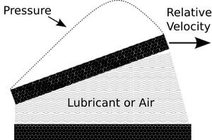
Each microcavity, whether it is a groove or dimple, acts as a miniature hydrodynamicW bearing during relative motion between the two contact surfaces.[1]This hydrodynamic effect is a result of the pressure gradient that forms in each pore, which can be modelled using the Reynold's averaged Navier-Stokes equationW.[5]With the relative motion between the two contact surfaces and the shear forces acting on the lubricant at the surfaces, a pressure profile is created due to the wedge effect (Figure 2). Microhydrodynamic bearings reduce the friction and wear between sliding surfaces. Lubrication is necessary for the microhydrodynamic bearing effect to become influential, as air has a very low viscosity relative to liquid lubricants. Non-lubricated surfaces required high relative speeds for this bearing effect to become relevant.
Debris Traps[edit | edit source]
The microcavities provide a sink for debris particles to fit into and reduce the associated additional friction of debris in the contact zone. The function of the pores as debris traps is found in both lubricated and non-lubricated applications, and is the main positive effect of surface texturing for non-lubricated applications.[4]
Lubricant Reservoirs[edit | edit source]
If an area of surface contact loses lubrication, the microcavities can provide additional lubricant that is drawn to the starved area through capillary actionW.[4]The patterned geometry allows for countless miniature lubricant reservoirs, providing direct and immediate lubricant relief for starved areas. In order for these reservoirs to exist, the geometries of the pattern microstructure must be closed to prevent lubricant from being forced out through channels.[6]
Applying the Technology[edit | edit source]
The creation of specific patterned surface microstructures can be achieved in many ways, for example abrasive blasting, reactive-ion etchingW, and ultrasonicW machining. However, laser technology offers the most control and precision over the produced geometry. Also, laser ablation does not use chemical reagents or produce significant waste. See the section below for alternative surface texturing methods.
To implement laser surface texturing, several technological decisions regarding the equipment and application need to be considered. These include the laser characteristics, the use of scanning or interference patterns, pore geometry and frequency, and full versus partial LST.
Lasers[edit | edit source]
In order to manufacture pattern surface microstructures, the laser used needs to be suitable for the workpiece material and capable of either melting or ablating the material. In practice, some of the main types of lasers utilized in LST are Nd: YAG laserW, carbon dioxide laserW, and excimerW lasers. The lasers are usually pulsed, often using a Q-switching setupW, to produce one dimple per pulse. With high repetition rates (pulse durations of μs to fs), thousands of dimples can be created in very short processing times. With possible speeds of well over 1000 microcavities produced per second, LST can be scaled to large areas.[6]
Nd: YAG and CO2 are more common than excimer lasers, as excimer lasers have comparatively low ablation rates and take excessive time for LST. On the other hand, due to the low abolition of excimer lasers, they can be used to create microstructures within micrometer precision. As well, excimer lasers are often used with lithography methods and etching procedures to create surface textures.
In laser machining, the material is removed either through ablation, melting, or a combination of both. Often, a high-pressure gas is introduced next to the laser focal point, which blasts away molten and sublimated material. Cutting and removal rates depend on the laser power, wavelength, pulse duration, and on the material properties of the workpiece; characteristics such as absorption, thermal conductivity, and thermal capacity. The hardness of the material does not affect its laser cutting rate, making LST effective on typically difficult substances like carbides and ceramics.
Direct Beam, Scanning, and Interference Patterns[edit | edit source]
In order to produce the patterned microstructures on the material's surface, the laser beam position relative to the surface has to be manipulated. There are three main techniques for controlling the laser ablation to create the desired patterns: Direct beam movement, scanning, and the use of interference patterns. The technique to be used depends on the workpiece geometry, the scale of production, and the budget.
Direct Beam[edit | edit source]
The direct beam methodology applies the laser beam directly to the material's surface. An ablation head focuses the laser and a high pressure gas line blows away melted and sublimated material. A mechanized system allows for the workpiece or the ablation head to be moved in controlled increments. By manipulating the relative position of the ablation head and the workpiece, along with the pulse duration of the laser, the frequency of surface depressions can be controlled.
Scanning[edit | edit source]
Another method of controlling the laser patterning is to utilize a scanning system. By reflecting the laser beam with a series of motorized mirrors, the laser beam can be quickly moved to the desired position for each microcavity to be created. These motorized mirrors, usually referred to as a mirror galvanometerW, can precisely and rapidly direct the laser beam to the desired contact point. To ensure the beam does not strike the surface on an angle, a flat field lens is utilized to ensure the beam and surface are perpendicular at the contact point.[6]
Interference Patterns[edit | edit source]
To create patterned grooves and crossed grooves, optical interferenceW patterns can also be used.[2]The interference pattern covers the size of the beam diameter and creates many microcavities at once. When two beams interfere with each other, constructive and destructive interference occur, creating parallel linear lines of light. If this pattern of laser light is directed at a material's surface for a given time, ablation and melting will occur, creating parallel linear grooves. The period of the linear grooves is given by the formula:
Period = λ/(2sin(α/2))
Where: λ is the laser wavelength, α is the angle between the laser beams.[2]
To create a crossed groove microstructure, a sample can be exposed in one orientation to create linear grooves, and then rotated 90° and exposed again to the light to create crossed grooves.
Pore Geometry, Size, and Frequency[edit | edit source]
The optimum patterning and geometry of micropores for the best tribological characteristics depend on several application factors and is not an exact science. With dimple-like depressions, it is found that the exact geometry is not significant compared to the ratio between pore diameter and depth, and the area fraction covered by pores.[1]The application factors that influence the optimum pore ratio and area fraction include:
- Load capacity
- Pressure
- Material
- Sliding Velocity

In general, the current studies report optimum pore area coverage of between 10% and 15%.[7], [8] As well, the optimum pore diameter in the general case is around 10 μm.[8]At larger pore diameters, the lubrication film clearance drops and a sharp rise in friction is found.
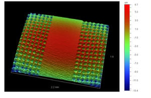
In certain high pressure applications, LST is found to be most effective when only partial areas ofthe contact surface are textured.[9] By only texturing a partial area, the load capacity between the surfaces can be much higher.[9]An image of an engine piston ring with partial LST is shown in Figure 3.
Finishing Procedures[edit | edit source]
Laser surface texturing relies on the target material being melted, ablated, and blown away by high pressured gas. After LST has been applied to a surface, excess melt rims and slag are present on the surface as an artifact from the laser processing.[4]These melt rims and excess resolidified material need to be removed through polishing in order for the intended surface geometry to function as expected. This polishing can be done with gentle abrasives and standard mechanical polishing techniques.
Coatings can also be applied after LST to improve surface characteristics. Films of materials like diamond-like carbonW and alloys of Ti can be applied to improve certain surface characteristics, such as hardness and wear.[4]
Benefits[edit | edit source]
Laser surface texturing has many benefits that could potentially save enormous amounts of energy and improve efficiencies of many mechanical systems. The most obvious benefit is a reduction of friction. As the field is relatively new, the number of variables in a LST application allow for a range of reported reductions of friction. The current studies indicate a substantial reduction in friction in the range of 20% – 65%.[2],[6],[10] The exact reduction in friction depends on a host of variables including load capacity, micropore geometry, velocity, and the materials used. This reduction of friction is true for both lubricated and dry cases, with lower friction reductions found for non-lubrication applications (15%-40%).[10]Solid lubricants, such as MoS2 and graphite, also can be used with LST surfaces and benefit from friction reduction.[11] The reduction of friction results in several benefits. First, the energy saved from being lost to heat can lower energy demands of the application. Secondly, the lower friction produces less heat, and therefore thermal stresses and strains at the surface are reduced. Finally, lower friction coefficients reduces stiction, allowing certain devices, such as MEMSW, to use lower forces to initiate motion.[12]
Another benefit is an improvement of fatigue life. The microcavities act as debris traps, saving small loose particles from initiating microfissures and damage. It has been observed that wear life of a component treated with LST has fatigue lifetime improvements of upwards of three times longer than a standard component.[2],[10]Wear caused by repeated small surface motions, known as frettingW wear, can be substantially reduced when LST is applied. Experiments have found that fretting fatigue life doubled with LST application.[13]
These impressive results from LST application show the potential that lies in this technology. Almost all mechanical systems combat friction in some way or another, and the applications for LST are continuous expanding.
Applications[edit | edit source]
Current[edit | edit source]
Being a relatively new field, LST is mainly in the research and small scale application stage. Currently, some LST commercial applications exist, such as a planned use of LST in a car engine production line and the use of LST in magnetic storage drives.[6],[14] Also, several specialty companies exists will texture provided parts and seals. Many investigations are underway involving different applications for commercial use including:
- HydraulicsW[6]
- Seals[3]
- Thrust bearingsW[3]
- Magnetic storage devices[14]
- MEMS devices[12]
- Engines[6],[15]
- Bone and dental implants with LST surfaces to improve osseointegration[16]
Ideas for Future Applications[edit | edit source]
As stated above, the potential for LST is enormous due to the volume of devices that incur significant loses to friction. Some ideas for future LST applications include:
- Linear bearings, rotary bearings
- FlywheelW energy storage
- Recreational activities and sports (skis, skates, games, sleds)
- Projectile acceleration through a tube (i.e. electromagnetic/railgunW satellite launch)
Case Example - Energy Balance[edit | edit source]
To emphasize the energy saved through LST application, a specific case example can be studied. Piston ringsW are suited for LST application due to the significant repeated relative contact between the rings and the cylinder wall. The following conservative parameters were used in this energy calculation:
- 5 kW CO2 laser
- 100 Pulses/second, each pulse creating a dimple-like impression
- 4 Cylinder engine
- 3 Piston rings per piston
- Piston rings are 2.5 mm wide, with a 100 mm radius, and the exterior radial surface is textured
- Square matrix of dimples with 0.5 mm spacing between dimples
Using these parameters, the energy consumed by the laser operation to texturize all 12 piston rings is equal to 3.8 MJ. To provide an approximation for the energy saved by this LST application, the results from a study involving LST application to a Ford Transit 4-cylinder diesel engine can be examined.[15]The study found fuel consumption decreased by approximately 4% when using the LST piston rings versus standard piston rings. To put these number in comparison, diesel has an energy content of 42 MJ/kg (approximately 80% of the energy content is transformable into thermal energy).[17] This example does not take into account many other small energy losses that would be incurred during the application of LST, only the laser energy expended, however it still demonstrates the very short energy payback period.
Alternative Surface Texturing Methods[edit | edit source]
The tribological improvements associated with surface texturing can also be achieved with other texturing techniques instead of LST. While lasers offer an unmatched precision and control, the following techniques are being used and investigated for surface texturing applications:[3]
- Abrasive jet machining
- Electrical Discharge MachiningW
- Ion beamW texturing
- Vibrorolling
- Reactive-ion etchingW
References[edit | edit source]
- ↑ 1.0 1.1 1.2 D.B. Hamilton, J.A Walowit, C.M. Allen, "A Theory of Lubrication by Micro-Irregularities", ASME Journal of Basic Engineering 88(1), 177-185.
- ↑ 2.0 2.1 2.2 2.3 2.4 M. Duarte, A. Lasagni, R. Giovanelli, J. Narciso, E. Louis, F. Mücklich, "Increasing Lubricant Film Lifetime by Grooving Periodical Patterns Using Laser Interference Metallury", Advanced Engineering Materials 10(6), 554-558, 2008.
- ↑ 3.0 3.1 3.2 3.3 I. Etsion, "State of the Art in Laser Surface Texturing", Journal of Tribology 127 (248). 2005
- ↑ 4.0 4.1 4.2 4.3 4.4 C. Donnet, A. Erdemir, "Tribology of Diamond-Like Carbon Films, Chapter 3: Laser Processing", Springer US Publishing. 2008.
- ↑ L. Burstein, D. Ingman, "Effect of Pore Ensemble Statistics on Load Support of Mechanical Seal with Pore-Covered Faces", ASME Journal of Tribology 121(1), 927-932, 1999.
- ↑ 6.0 6.1 6.2 6.3 6.4 6.5 6.6 A. Hoppermann, M. Kordt, "Tribological Optimisation Using Laser-Structured Contact Surfaces", Oelhydraulik und Pneumatik 46(4), 2002.
- ↑ H.L. Costa, I.M Hutchings, "Hydrodynamic lubrication of textured steel surfaces under reciprocating sliding conditions", Tribology International 40(8), 1227-1238, 2007.
- ↑ 8.0 8.1 M. Mahbubur Razzaque, M. Tanvir Rahman Faisal, "Performance of Mechanical Face Seals with Surface Micropores", Journal of Mechanical Engineering 37(1), 2008.
- ↑ 9.0 9.1 Y. Kligerman, I. Etsion, A. Shinkarenko, "Improving Tribology Performace of Piston Rings by Partial Surface Texturing", Journal of Tribology 127(3), 632-639, 2005.
- ↑ 10.0 10.1 10.2 I. Etsion, "Improving Tribological Performance of Mechanical Components by Laser Surface Texturing", Tribology Letters 17(4), 733-737. 2005.
- ↑ .A. Voevodin, J.S. Zabinski, "Laser Surface Texturing for Adaptive Solid Lubrication", Wear 261(11), 1285-1292. 2006.
- ↑ 12.0 12.1 K. Komvopoulos, "Adhesion and friction forces in microelectromechanical systems: mechanisms, measurement, surface modification techniques, and adhesion theory", Journal of Adhesion Science & Technology 17(4), 477-517, 2003.
- ↑ A. Volchok, G. Halperin, I. Etsion, "The effect of surface regular microtopography on fretting fatigue life", Wear 253(3), 509-515, 2002.
- ↑ 14.0 14.1 B. Raeymaekers, I. Etsion, F.E. Talke, "Enhancing tribological performance of the magnetic tape/guide interface by laser surface texturing", Tribology Letters 27(1), 89-95, 2007.
- ↑ 15.0 15.1 I. Etsion, E. Sher, "Improving fuel efficiency with laser surface textured piston rings", Tribology International (In Press), Available online April 15, 2008 at: http://web.archive.org/web/20100306192703/http://www.sciencedirect.com:80/science/article/B6V57-4S92XSP-1/2/fd392ac261846c9ae6e6be66d42c7dfd
- ↑ M. Marticorena, G. Corti, D. Olmedo, M.B. Guglielmotti, S. Duhalde, "Laser surface modifications of Ti implants to improve osseointegration",Journal of Physics: Conference Series 59(1), 662-665, 2007.
- ↑ Food and Agriculture Organization of the United Nations, "Utilization of renewable energy sources and energy-saving technologies by small-scale milk plants and collection centres", FAO Animal Production and Health PApers 93(1), 662-665, 1992. Available online at: http://www.fao.org/docrep/004/t0515e/T0515E08.htm