Charcoal Cooler
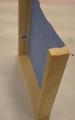
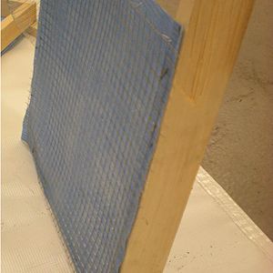
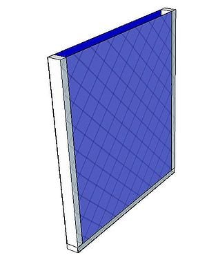
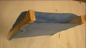
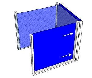
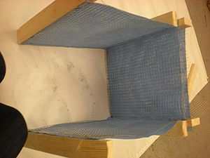
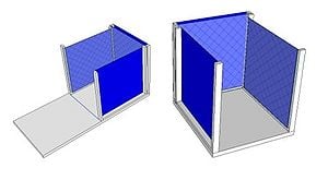
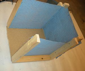
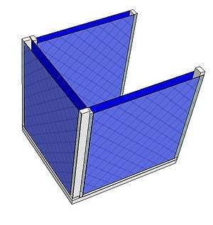
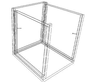
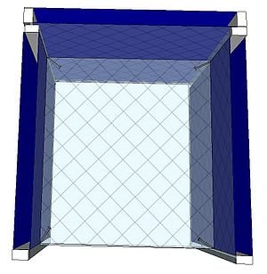
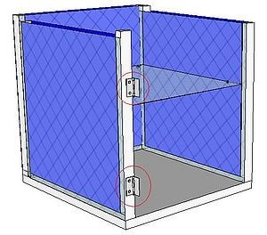
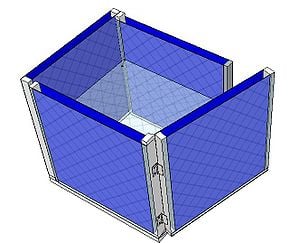
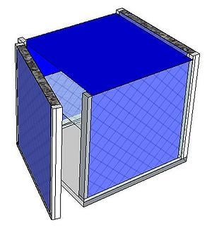
A charcoal cooler uses the principal of evaporative cooling to maintain a cool interior temperature for refrigeration and food preservation. The device is constructed from an open timber frame with charcoal filled sides, which is kept continually moist. As warm, dry air flows through the moist charcoal, water is evaporated into the air and it is cooled. The basic principles of heat and mass transfer underlie the function of the charcoal cooler. A simplified analytical model was developed in Engineering Equation Solver (EES) to determine the functionality of the charcoal cooler for a variety of outdoor conditions and design variables. It was found that the dimensions of the cooler have minimal impact on the maintained interior temperature, however ambient conditions significantly impact the device functionality. A prototype cooler was built to develop detailed construction instructions. Future work on this project would include testing of the prototype for model validation. The EES model, CAD file, and printable PDF documents are available in Additional Documents.
Developmental Need[edit | edit source]
Evaporative cooling can be used to address two main developmental needs: space cooling (air conditioning) and refrigeration. The charcoal cooler addresses the need for refrigeration in areas where electricity is unavailable.
Refrigeration of food is a method of slowing bacteria growth and extending shelf life. Typical refrigerators are kept around 2-3 degrees C° and can extend the shelf life of produce by weeks.[1]
In hot climates where electricity is unavailable, refrigeration of food is a developmental need. In Sudan, for example, tomatoes will only last 2 days in the hot sun.[2] Preservation of crops through refrigeration can help with hunger and starvation in the developing world by keeping foods fresh longer. In areas with no electricity, refrigeration is particularly challenging, and has lead to the design of a variety of heat driven refrigeration devices, including evaporative coolers. While these devices are not typically capable of maintaining temperatures of 2-3 degrees Celsius, they can be significantly cooler than ambient temperature, and even moderate drops can significantly extend the shelf life of produce. For example, when housed using a similar evaporative cooling device, the life of tomatoes can be extended from 2 to 20 days.[2] Evaporative cooling has an added benefit of increasing the air moisture content, preventing food from drying out and further extending shelf life.[3]
Refrigeration is also important for vaccine and medicine storage, however the required temperature drop and temperature control make evaporative cooling unsuitable for this application.
Climatic Limitations[edit | edit source]
As discussed further below in engineering principles, the potential for evaporative cooling depends on the difference in wet bulb and dry bulb temperatures of the air. Humid air has a high relative humidity, and not as much capability to evaporate moisture. As the relative humidity of the air increases, the performance of the system will decrease, limiting its application in moist climates. Evaporative cooling is most effective in climates where relative humidity is less than 30%.[4] As humidity increases, the cooling capability declines, and the temperature difference between the outside and inside of the chamber decreases. To test if evaporative cooling will be effective, the wet bulb temperature can be measured by placing a moist cloth on the end of a thermometer and waving it through the air.[3] The temperature read by the thermometer is the theoretical minimum temperature that can be achieved through evaporative cooling.
Additionally evaporative cooling must be used in areas where water is available. Depending on the conditions, and cooler dimensions, the device may use 20-70L of water per day when working effectively.
Scientific Principles[edit | edit source]
Evaporative cooling is based on the principle that water requires heat energy to evaporate. In hot, relatively dry climates the evaporation of water into hot, dry air can create a cooing effect, suitable for space conditioning or refrigeration. The heat removed from a space due to the evaporation of water is given by equation 1.
(1)
Q is the heat removed in kW, is the rate of evaporation of water in kg/s, and he is the latent heat of evaporation for water (~2270kJ/kg).[5] The cooling capacity is therefore approximately proportional to the rate of evaporation of water, which depends on:
- Ambient Temperature
- Ambient Humidity
- Surface Area
- Evaporative Media
- Air Movement (natural or artificial)
To maximize the cooling effects these variables must be optimized for a given application.
Psychrometrics[edit | edit source]
Evaporation, the process of changing water from a liquid to a gas, requires heat from the surrounding environment. Psychrometric properties of moist air, as well as the principals of heat and mass transfer apply to the evaporation of water for cooling. Understanding the properties of moist air is key in understanding how evaporative cooling works.
Moist air is air consisting of water vapour, and dry air. The total pressure of the air is the sum of the partial pressures of the water vapour and the dry air, as shown by equation 2.
(2)
Saturated air is a mixture of dry air and saturated water vapour. When air is saturated the vapour pressure Pv is equal to the saturation pressure Pv,max of water at the temperature of the air. Since saturation pressure increases with temperature, air at a higher temperature has the capacity to hold more moisture.
Humidity refers to the amount of moisture in the air, and can be expressed in two ways. Relative humidity, equation 3, is the ratio of moisture in the air to moisture in saturated air at the same temperature.
(3)
Relative humidity is therefore a function of both temperature and moisture content.
Absolute humidity is the ratio of the mass of water to mass of dry air, and is given by equation 4.
(4)
Absolute humidity is therefore only a function of the moisture content.
The driving force behind the evaporation of air is the difference in vapour pressures between the air and water. Air at a higher temperature and lower relative humidity is able to evaporate more moisture than cool or moist air. The potential for evaporation is proportional to the difference in dry bulb and wet bulb temperatures. The dry bulb temperature measures the temperature of the air stream whereas the wet bulb temperature is representative of both the temperature and humidity. Wet bulb temperature can be measured by placing a moist cloth on the end of a thermometer and allowing air to pass over it while reading the temperature. The relative humidity and absolute humidity can then be determined from a psychometric chart.
Evaporation[edit | edit source]
Evaporation is the change in state between a liquid and a gas. For water and air, evaporation involves liquid water vapourizing into a moist air stream. For the purpose of the Charcol Cooler model, two simplified mass transfer cases were consdered: evaporation from a surface, and evaporation through a transfer medium.
Evaporation from a Surface[edit | edit source]
A simple empirical correlation can be used to estimate the rate of evaporation of water from a surface. Figure 1 shows a schematic.

Equation 5 gives the empirical correlation for the evaporation rate me in kg/h.[6]
(5)
is the saturation absolute humidity at the ambient temperature and is the actual absolute humidity. A is the water surface area.
Evaporation Through a Transfer Medium[edit | edit source]
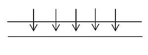
Many evaporative cooling units pass air through a porous soaked pad that is kept replenished with water. Figure 2 shows a schematic.
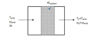
The evaporative efficiency of the medium is given by equation 6.[7]
(6)
It should be possible to achieve 60-90% efficiency; however efficiency values for specific media can be determined experimentally.[3] An energy balance on the air stream gives the rate of evaporation, expressed in equation 7.
(7)
ha is the enthalpy of dry air, hw is the enthalpy of water vapour and hf is the enthalpy of saturated liquid at the temperature of the water in the pad. The rate of evaporation can then be determined from equation 8.
(8)
is the mass flow rate of the air traveling through the soaked pad.
Fundamental Heat Transfer[edit | edit source]
Heat is transferred through conduction, convection and radiation. Often the effects of radiation can be ignored, as they are small when compared to other forms of heat transfer. Conduction occurs through a solid surface and is given by equation 9.
(9)
is the heat transferred in Watts (W), k is the conduction coefficient in W/mK, t is the thickness of the solid in meters and delta T is the temperature difference across the solid. The conduction coefficient is a property of the material and can be found in literature or experimentally.
Convection occurs from a fluid passing over a solid object and is given by equation 10.
(10)
h is the convection coefficient, A is the area, T is the temperature of the solid object and is the temperature of the fluid. The convection coefficient is a function of the fluid velocity, fluid properties, and object dimensions. It can be determined experimentally or from derived correlations.
Device Construction[edit | edit source]
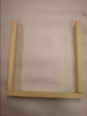
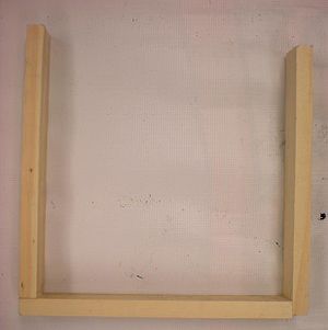
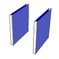
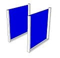
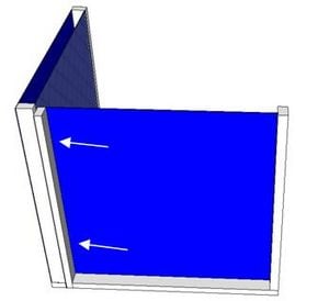
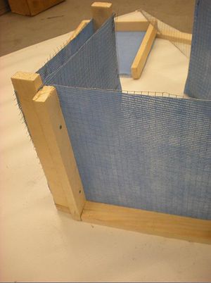
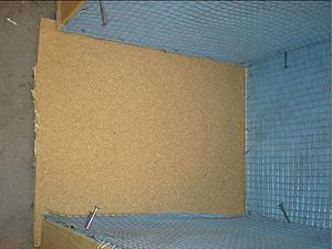
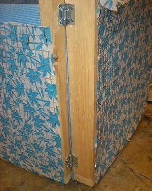
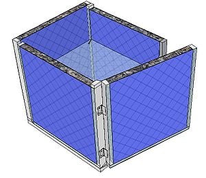
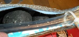
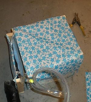
A prototype charcoal cooler was constructed. The materials used, and detailed construction instructions are below. The prototype charcoal cooler was 1ft x 1ft x 1ft but instructions should apply regardless of device size. One of the advantages of this device is that it is versitile and can be made out of many available materials, therefore substitutions are suggested.
A printable PDF including materials, construction details, and operation instructions for the cooler is included in Additional Resources.
Required Materials[edit | edit source]
| Material | Picture | Alternate | Approximate Cost ($ CA) |
|---|---|---|---|
| Wood 12 ft of 1cm x 2cm timber |
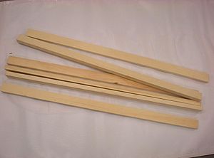 |
Wood of another size is usable. Bamboo or any other structural material will also work. | $2/3ft ($8 total) |
| Mesh Chicken Wire Approximately 10sq.ft is required |
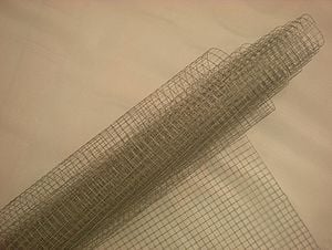 |
$8/roll | |
| Cloth Jute cloth or canvas: approximately 12sq.ft is required |
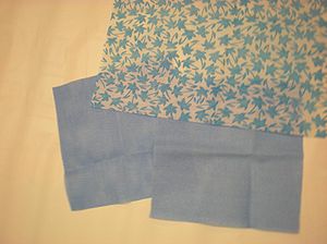 |
Another absorbent cloth material may be used. | $1/12sq.ft |
| Nails Finishing and carpentry nails |
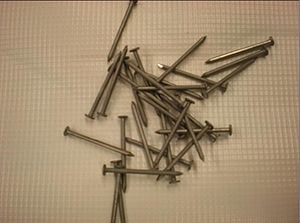 |
Screws can be used in place of carpentry nails. If available, a staple gun and staples to replace the finishing nails would make construction significantly easier. Twine or rope can be used to lash frame together if necessary. | $2/package |
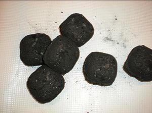
| Charcoal Approximately 4kg |
 |
Another absorbent material will suffice as long as it allows for air circulation, can hold a substantial amount of moisture, and can be contained within the frame of the cooler.[3] | $10/package |
| 2 Hinges | 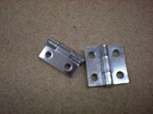 |
$3/package | |
| Solid Board 1 peice, approximately 1ft x 1ft (dimensions of the base of the cooler) |
 |
Woven bamboo or reeds can be used to replace the board. | $1 |
| Plastic Hose Approximately 10ft 1/2-1 inch in diameter |
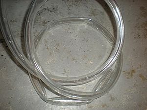 |
Alternately, tins can be placed on the top of the cooler if hose is unavailable. This modification will be discussed further in the construction instructions. | $7.60/10ft (5/8" D) |
| Ties Approximately 8 plastic tie devices |
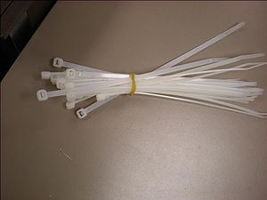 |
Twine or string is a good alternative for the ties. | $2/package |
| One Bucket Any size |
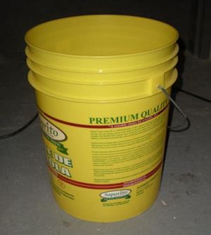 |
Any device that can hold water can be used. If tins are used instead of hose the bucket is unnecessary. | $5 |
| Tools A hammer, saw and scissors or wire cutters are required |
 |
A screwdriver can be used if screws are substituted for nails. A staple gun would assist with construction. If twine is used to lash frame together, a hammer is not required. |
The total materials cost is therefore $48.00. The cost can be reduced by using alternate or recycled materials.
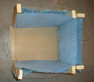
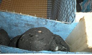
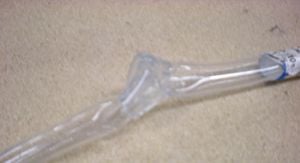
Tie the end of the hose. Pour some water into the hose to ensure the tie is sufficient to block the end of the hose. If tie is not sufficient, a stopper must be used to prevent water from flowing through the hose. If hose is unavailable and tins are used, the tins can be fastened to the top of the frame, with holes poked by nails on the charcoal cavities. If this method is used it is recommended that the tins have lids to prevent evaporation of the water from the surface of the tins.

Device Operation[edit | edit source]
Produce can be placed on the shelf or on the bottom of the cooler. The device should be placed in the shade with one side facing into the wind. Artificial air circulation with a fan may also be used. Very little maintenance is required however when first constructed the cooler should be monitored to ensure effective moistening of the charcoal.
Model Development[edit | edit source]
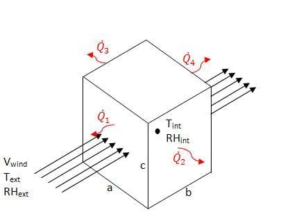
An EES model of the charcoal cooler was developed to determine the effect of various design variables as well as ambient conditions. The charcoal cooler was modeled as a control volume with one face normal to the ambient wind. The EES file is available for download in Additional Documents. Figure 3 shows a schematic of the modeled system.
Figure 3: Charcol Cooler Model Schematic
The following assumptions were made for the analysis:
- The conditions are at steady state
- The cooler will be placed in a shaded region and radiation effects are negligible
- The top and bottom of the cooler are insulated (no heat transfer)
- The heat of vaporization of water is constant and 2270kJ/kg
- No heat is generated inside the cooler
- The entire system operates at atmospheric pressure (101.325kPa)
- The charcol is kept continually moist (water flow = rate of evaporation)

The heat transfer through each side of the cooler was considered individually, and is explained below.
The model is available for download in Additional Documents. The diagram view of the model allows the user to input ambient conditions (T, RH, Wind Speed), evaporative efficiency, and cooler dimensions and outputs the interior conditions and rates of heat transfer.
Side 1[edit | edit source]
The front side of the cooler can be modeled as air flow through a moist pad. Figure 2, above, is therefore a schematic for the air flow through the front of the cooler. The equations listed in Evaporation through a Transfer Medium apply. The heat transfer is equal to the rate of evaporation times the enthalpy of vaporization. The temperature internal to the cooler Tint is calculated based on the evaporative efficiency and ambient conditions, as given by equation 6. This temperature is assumed to be constant over the width (b) of the cooler. The internal temperature is therefore dependent on the ambient conditions and evaporative efficiency.
Sides 2 and 3[edit | edit source]
Sides 2 and 3 of the cooler have the same heat transfer rate, however unlike side 1 the rate of heat transfer is dependent on more than the rate of evaporation. Figure 4 shows a schematic of the side wall as viewed from the top.
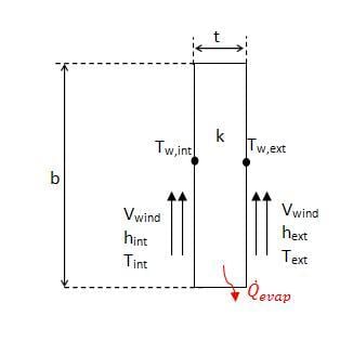
As shown in the figure, there is convection over the surface, as well as evaporative heat loss from within the wall. It was assumed that the evaporation only occurs on the inside and outside surfaces of the wall, and that it could be modeled using equation 5, the correlation for free surface evaporation.
The convection coefficients were calculated using the empirical correlation for forced convection over a flat plate with a constant heat flux, as given by equation 11.[8]
(11)
Nu is the Nusselt numberW, Re is the Reynold's NumberW, and Pr is the Prandtl numberW.
Applying the stated assumptions, the wall was modeled using a thermal resistance network, as shown below in figure 5.

As evident from the figure, for heat to be removed from the inside of the device, the sum of the evaporative heat removed must be greater than the heat added from convection. The conduction coefficient for charcoal was assumed to be the same as wood, approximately 0.16W/mK.[9]
Side 4[edit | edit source]
The back of the cooler allows for constant air flow through the device, and may further cool the air stream if air is not saturated. The evaporation would cause cooler air to exit the device but would have little to no effect on the temperature inside the cooler. The heat transfer through the back face of the charcoal cooler was assumed to be negligible and was not considered in the model. The design of this back face is further discussed in design recommendations.
Model Analysis[edit | edit source]
Using the analytical model described in Model Development, the design parameters were analyzed to determine the performance of the device under a variety of conditions.
The rate of heat transfer () for sides 1, 2, and 3 was calculated and is shown in figure 6 as a function of the ambient temperature (T1).
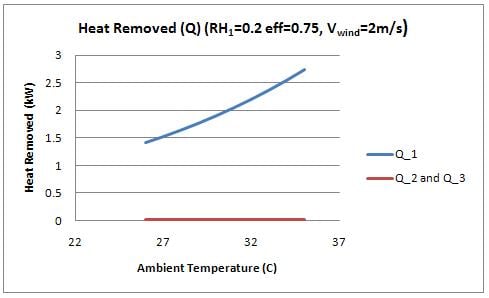
Two interesting observations are displayed in this figure. First, the heat removed by side 1 (facing into the wind) is significantly greater than the heat removed from the sides of the device. It was therefore assumed for the analysis that temperature inside the cooler is constant, and a function of the evaporation through the front of the cooler. The evaporation in the sides of the cooler essentially "cancel" out the heat that would otherwise be added to the inside by convection. By this effect, the side walls are essentially acting to insulate the device. The device would perform comparably with insulated side walls (using a foam or equivalent insulation material). Insulating the walls will reduce the amount of water use required significantly, however orientation of the device would become a prime consideration. This idea is further discussed in design recommendations.
Figure 6 also shows that the heat removed from the front face increases with temperature, which is explained by the increased evaporation rate with temperature.
The temperature inside the chamber was examined as a function of the ambient conditions (temperature and humidity). Figure 7 shows the plot.
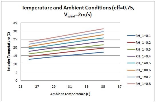
The interior, cooled temperature is therefore much lower for conditions with low relative humidity. While the heat transfer rate increases with temperature (as shown by figure 6), the interior temperature is lower with lower ambient temperatures because the required temperature drop is not as large. At high humidity, the device does not provide enough cooling to successfully refrigerate produce. For the interior temperature to be below 20 degrees Celsius, the humidity must be below 0.5.
For previous figures, the evaporative efficiency was assumed to be 0.75. It should be possible to achieve a value of 0.6-0.9 with charcoal.[3] Figure 8 shows the effect of evaporative efficiency on interior temperature.
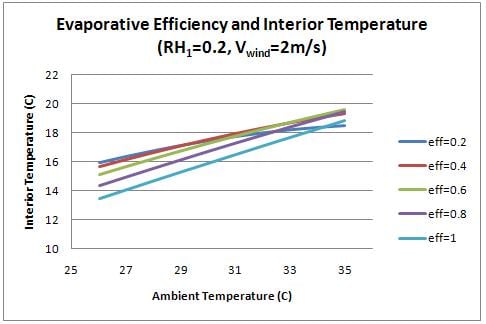
Higher evaporative efficiency can significantly increase the cooling capacity of the cooler. Future work should be done to determine the factors that affect this parameter, and how to best optimize the efficiency of the charcoal medium.
Finally, the evaporation rate through each side of the container was examined as a function of the ambient conditions. Figure 9 shows the evaporation rate though the front (side 1) and figure 10 shows the evaporation rate through the sides (2 and 3).
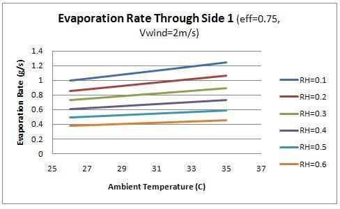
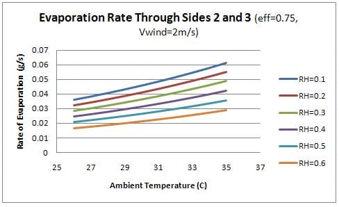
From the figures, it is evident that the evaporation through the front face of the box is significantly higher than the remaining faces. This observation relates to the design of the device as the water should flow into the charcoal sides as quickly as it is evaporating. Therefore the flow rate of water into the front face of the device should be significantly higher than the remaining sides. This concept is discussed further in design recommendations.
Design Recommendations[edit | edit source]
Based on the prototype construction and model analysis the following recommendations are made for the design of the cooler:
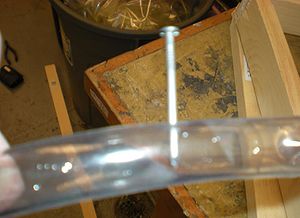
- The flow rate of the water into the cooler is an important parameter that depends on ambient conditions and the tubing or tins used. The flow rate should be equal to the rate of evaporation to ensure that water does not leak from the cooler, and that the charcoal does not dry. It is recommended that the holes in the tubing on the front side of the device be made larger and closer together than the other two sides.
- Depending on the availability of charcoal the back face of the cooler does not require the charcoal medium since evaporation from this face does not contribute to the cooling effect. It may, however, be useful to include charcoal on all sides so that orientation and wind direction does not matter.
- The side walls of the device could be insulated to reduce the required water use. Using an available insulation material inside the wooden frame would prevent heat transfer through convection, but would not require evaporation. Should the side walls be insulated, the device orientation is very important, as the device will NOT perform if the wind is not incident on the front face. If an electric fan is available to generate a forced air-flow in a controlled direction, it is recommended that the side walls be insulated. If the device is to use natural air flow from the wind the user may insulate the side walls but must maintain the device to ensure proper orientation despite changing wind patterns.
- The tins or bucket of water should be covered to prevent evaporation into the ambient environment.
- It was found through the model that the dimensions of the cooler do not greatly affect the performance. Some of the model assumptions, however, do not hold true with large dimensions. Based purely on construction, it is easiest to construct a cube-shaped cooler since all pieces of wood can be cut to the same size.
Cost Analysis[edit | edit source]
A simple economic analysis was performed (using Canadian figures) to determine the cost of the device over its lifetime. Materials costs are given above in Required Materials.
Please note the first costs, labor and rates are highly dependent on the location.
First Costs:
| Item | Cost per Unit | No. Units | Total Cost |
| Materials | |||
| $48.00 | |||
| Labour | $9.50/hour[10] | 3 | $28.50 |
| Total | $76.50 |
|---|
Operational Costs:
| Item | Cost per Unit | No. Units | Total Cost |
| Water | 0.86/1000L[11] | 100L/day* | $0.086/day |
- *This is a conservative estimate as water use depends greatly on the climate. Future work can address modeling this water use as a function of climate and geography.
The cost is highly dependent on the cost of water and labour for the given region. Alternative materials and lower labour costs can significantly reduce the first cost of the device. Additionally, the cost of water is region dependent, and should be calculated for the specific region the device is to be used. The above "operational costs" are merely an example. The operational costs shown do not include the labour costs of traveling to collect the water, which may be non-trivial in some regions.
Additional Documents[edit | edit source]
- Media:CC ConstructionInstructions.pdf - Printable version of the detailed instructions for device construction
- Media:CC Science Model.pdf - Printable version of the scientific principles, model development, and model analysis
- http://sketchup.google.com - The software is available for download
References[edit | edit source]
- ↑ "Fruits and Vegetables: Optimal Storage Conditions." Engineering Toolbox 2005. Accessed Online: April 8th 2010. Available <http://www.engineeringtoolbox.com/fruits-vegetables-storage-conditions-d_710.html>
- ↑ 2.0 2.1 "How a zeer pot fridge makes food last longer." Practical Action 2009. Accessed Online April 8th 2010. Available: <http://practicalaction.org/?id=zeerpots>
- ↑ 3.0 3.1 3.2 3.3 3.4 3.5 3.6 Rusten, Eric. "Understanding Evaporative Cooling." VITA 1985. Accessed Online: April 8th 2010. Available: <http://www.fastonline.org/CD3WD_40/VITA/EVAPCOOL/EN/EVAPCOOL.HTM>
- ↑ Moran, M. J., Shapiro, H. N. Fundamentals of Engineering Thermodynamics. Ed. 6. John Wiley & Sons Inc. USA: 2008. P. 686.
- ↑ Moran, M. J., Shapiro, H. N. Fundamentals of Engineering Thermodynamics. Ed. 6. John Wiley & Sons Inc. USA: 2008. P. 817.
- ↑ "Evaporation from Water Surfaces." Engineering Toolbox 2005. Accessed Online: April 8th 2010. Available <http://www.engineeringtoolbox.com/evaporation-water-surface-d_690.html>
- ↑ "Evaporative Cooling Basics." Western Environmental Services Corporation: 2009. Accessed Online: April 8th 2010. Available: <http://web.archive.org/web/20171019165521/http://www.wescorhvac.com:80/Evaporative%20cooling%20white%20paper.htm>
- ↑ Incropera, F. P., DeWitt, D. P. Fundamentals of Heat and Mass Transfer. Ed. 6. John Wiley & Sons Inc. USA: 2007. P. 413.
- ↑ Incropera, F. P., DeWitt, D. P. Fundamentals of Heat and Mass Transfer. Ed. 6. John Wiley & Sons Inc. USA: 2007. P. 940.
- ↑ "Ontario's Minimum Wage Increase." Government of Ontario 2010. Accessed Online: April 10th 2010. Available: <http://web.archive.org/web/20140108012445/http://www.labour.gov.on.ca:80/info/minimumwage/>
- ↑ "Municipal Water Pricing Report." Water.org 2008. Accessed Online April 10, 2010. Available:<http://www.priceofwater.com/municipal-summary.html>
