Blender Design on Curved Surfaces Tutorial
There are many ways to get a flat design or photo extruded. However, this page will not highlight these methods. If you are interested in extruding a flat image to use in the next steps, download Inkscape and a generate path to OpenSCAD extension. There are numerous pages dedicated to this method, so google away!
UPDATE April 30, 2019: I've also taken the liberty of recording my entire process from inkscape to blender on an Xbox One S Controller Faceplate due to popular demand on thingiverse. This may help answer any questions you might have along the way. You can find the [Tutorial Video] by clicking on the name.
Also, due to the many confusing versions of inkscape extensions of Paths2openscad, you can find the link to the two extension files [here]. These can be pasted in the following path: ~Inkscape\share\extensions (IF YOU'RE USING WINDOWS, USE THIS PATH: C:\Program Files\Inkscape\share\extensions).
Step 1[edit | edit source]
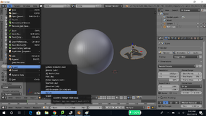
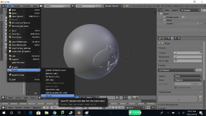
- Import the .stl files you intend to use. For the purposes of this tutorial, I simply generated a sphere and imported a Michigan Tech Logo .stl that I
generated using Inkscape to OpenSCAD. You can find the import path in Figure 1.
Step 2[edit | edit source]
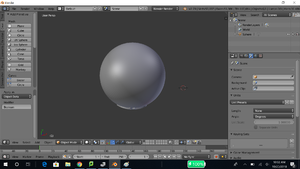
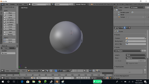
- In Blender, after your .stl is uploaded, translate the .stl's so you can see both. Sometimes during an import, you may have to scale or translate the .stl you have imported.
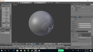
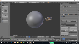
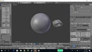
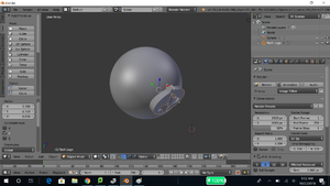
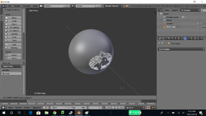
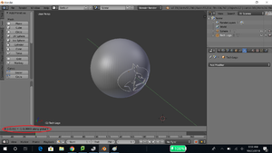
- Once you can see both objects, scale your flat extrude in the face direction. For example, Figures 2 and 3 show a before and after. I scaled the Michigan Tech Logo .stl in ONLY THE Y DIRECTION. This extended my logo extrude to where I can have the entire surface of the sphere covered when intersecting the logo .stl. This part will make more sense if you view Figure 5 found in Step 3.
- Some useful shortcuts to use in blender:
- to scale in a given direction, press S on the keyboard, then press X, Y, or Z on the keyboard to select a scaling direction. Simply type or move your mouse for the magnitude of the scale.
- to translate in a given direction, press G on the keyboard, then press X, Y, or Z on the keyboard to select a translation direction. Simply type or move your mouse for the magnitude of the translation.
Step 3[edit | edit source]
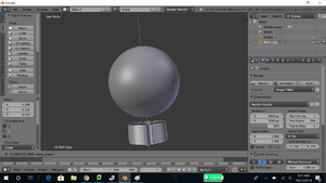
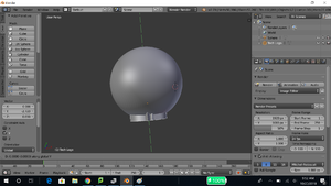
- After extruding the logo to the thickness needed, translate the logo so that it COMPLETELY intersects through the curved surface. If you are doing this on a cylinder, make sure to only go through ONE wall. DO NOT extrude all the way through the other side wall. Notice how in Figure 5, the extrude goes in one side of the sphere and does not come out the other. Be careful to only extrude to completely intersect the curved surface.
- Figures 4, 5, and 6 show how to intersect with the curved surface. Refer to Step 2 for shortcuts in translating.
Step 4[edit | edit source]
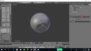
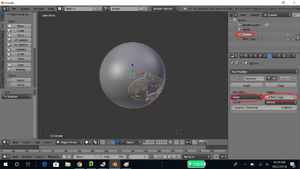
- After your part is aligned and intersected with the curved surface, select the wrench as shown by the red circle in Figure 7.
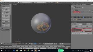
- Make sure your logo or design .stl is selected in the top right window, as shown by a red circle in Figure 9.
- Your part should have an orange highlight around it.
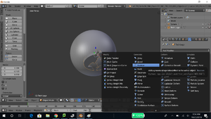
- As shown in Figure 8, click add modifier, then select Boolean.
- Shown in Figure 9 with two red circles, select Intersect and the curved object.
- Your logo or design should be in orange matching the curvature of the curved surface.
- Click Apply.
Step 5[edit | edit source]
EDIT!!!!! PLEASE READ!
- Instead of using the scaling method (as seen below), do this instead:
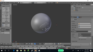
- After completing the intersect boolean operation, select your logo or design again. You'll notice now that it has the same curve as the surface of the curved object shown in Figure 10.
- Translate the intersected logo as far forward as you want it to stick out (if you want to have it engraved, see the following engrave directions. Engraving typically produces better results when 3D printing in my experience).
- Refer to Step 2 for translating shortcuts
- Move on to the next step.
OLDER WAY, BUT STILL WORKS
- After completing the intersect boolean operation, select your logo or design again. You'll notice now that it has the same curve as the surface of the curved object as shown in Figure 10.
- Scale the logo or design by 1.1 in the face direction. In my example, I scaled by 1.1 in the Y direction, as shown in Figure 11.
- Refer to Step 2 for scaling shortcuts
- Translate the logo or design by a small amount(to make up for the cross over from scaling) in the face direction, outward away from the curved surface. In my example, I translated by -1.0 in the Y direction as shown in Figure 12.
- Refer to Step 2 for translating shortcuts
ENGRAVING rather than RAISED LOGO
- After this direction, do not go forward to the union steps. Simply export after these directions if you intend to have this item engraved.
- After completing the intersect boolean operation, select your logo or design again. You'll notice now that it has the same curve as the surface of the curved object shown in Figure 10.
- Translate the intersected logo FORWARD (out of the face of the object your engraving) about the same distance as the depth of the engraving you want to have on your object.
- Perform a difference boolean this time (you should still be selected on the logo or design).
- Now translate your logo or design back into the face, until it just barely sticks out past the surface of the face. (IMPORTANT! If you try to make it flush and perform the next boolean, you may end up with manifold edges or an imperfect mesh)
- Select the object you are trying to engrave now. Perform a difference boolean (Have the engraved object highlighted when you perform the boolean).
- Delete the logo or design you have engraved.
- SKIP to Step 7

Step 6[edit | edit source]
- At this point, the shape you want should be achieved. The rest of this step is cleanup.
- As shown in Figure 13, select your curved object, NOT your logo or design.
- Select Add Modifier and choose boolean, the same process as in Figure 8.
- Select Union and your logo or design as shown by the Red circles in Figure 13.
- Click Apply
- Now select your logo or design on the top right hand window.
- Right click and delete the logo or design object.
- Your logo should still be in place because of the union even after deleting the object
- Right click and delete the logo or design object.
- Your final design should have a top right window as shown in Figure 14.
Step 7[edit | edit source]
- Once your design is complete, export it as an .stl as shown in Figure 15.
Final Result[edit | edit source]
- This is the final result of this tutorial. I've done several similar designs with mugs and controllers and such, so I can confirm this works with many different curved surfaces.
