Optimization and CFD analysis of wind-powered water pump system
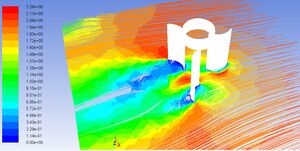
Access to safe water is an issue for 884 million people worldwide, and a part of this problem stems from inability to pump water from wells and difficulties in moving water from one area to another. Improved blade design in wind-powered water pumps has the potential to alleviate these difficulties. This analysis investigated improved wind turbine blade designs in which blades pivoted out of the wind when not in use. Using locally sourced materials and labour, the design cost was found to be under two days' wage for the Southern Asian regions in which it would be built. The comparative computational fluid dynamics analysis found that torque could be increased by a factor of 2.35 through two factors resulting from blade pivots: the first was decreased drag on unused blades, and the second was increased torque power-producing blades due to increased wind availability. A proof of concept was also conducted in order to confirm computational models.
Overview[edit | edit source]
The purpose of this page is to provide engineering analysis to pre-existing wind-powered water pump systems in the developing world. These devices, known as windpumps, have already been investigated but much work remains to be done in improvement and optimization. Historically, wind power was first used in mechanical systems to pump water and is still used for this purpose throughout the developing world.[1] In general, systems in the developing world are constructed by invididuals or communities using available materials: as such, it may be both disempowering and ineffective to create a wind pump design that uses only parts available in the western world. The following analysis was therefore conducted using only dimensions and generic wind speed correlations that can be used in any geography, provided that members of the community deem the use and effects of the analysis appropriate. The designs found in this analysis are also subject to material and labour time constraints: the design is left to the builder to modify as they see fit. As such, the scope does not include instructions for local construction of the blades.
The analysis conducted consists of two parts:
1) Design of a novel method of improving a standard vertical axis wind rotor for use in areas with low and variable wind speeds.
2) Computational Fluid Dynamics (CFD) analysis of the new rotor in order to locate possible improvements.
Background and Literature Review[edit | edit source]
Issues in Water and Sanitation[edit | edit source]
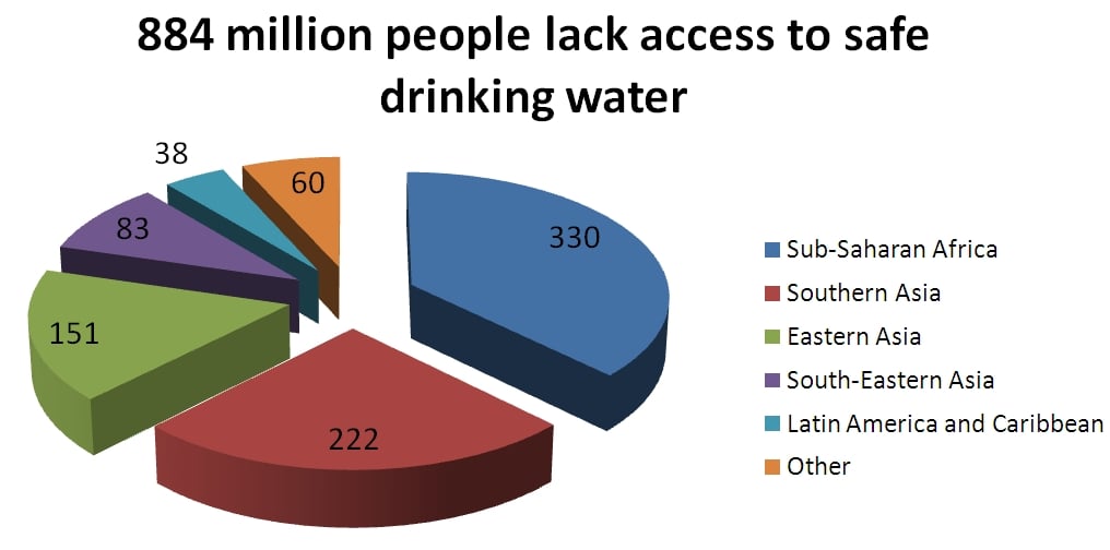
In 1995, 1.17 billion people lacked access to safe drinking water.[2] Access to drinking water in the world is improving, and is expected to reach the Millenium Development Goal target of 88% of the population having access to safe drinking water by 2015. However, 884 million people still lack the ability to meet this vital human need. A regional breakdown of this number is show in Figure 1 below.[3]
Because pumps are needed to provide drinking water when surface water is contaminated or far away, power is needed to supply safe water in some areas of the world. Wind power has been suggested as a possible renewable, sustainable, and passive source for energy to move water to areas in which it is required.[4] It has also been used in many projects to provide safe water.[5]
The availability of water sources is very important to improving safe water site use worldwide. As referenced in the WHO "Water for Life" programme, "Interruptions to drinking-water supply either through intermittent sources or resulting from engineering inefficiencies are a major determinant of the access to and quality of drinking-water."[6]In the design of a wind turbine for water pumping, this means that two engineering factors must be taken into account. First, the turbine must be sited in an area where wind speeds are consistent both throughout each day and seasonally. Second, a turbine must be designed that can both use wind from any direction, and function at low wind speeds.
Wind power for water pumping[edit | edit source]
Wind power has been used to pump water in development projects since the 1970s,[4] and work in the area has been increasingly driven by the increasing price of fossil fuels. In particular, design work has focused on vertical axis wind turbines due to their simplicity, low cost and the advantages of having rotational energy available at the hub.[5] While these turbines provide a relatively low amount of power due to the limitations of power density in wind power, they can provide between 3 and 5 meters of head in a water system, which is more than sufficient for vertical or horizontal pumping.[5] However, in order to provide optimal service, the wind turbine must be sited in a consistently windy area. Further information on siting wind turbines can be found in a wind turbine siting handbook.
The amount of water pumped and the height to which is can be pumped is determined by the power of the wind turbine. The energy available from the wind is derived using a streamtube through the swept area of a wind turbine. Total power is given by:
Where:
- P is the power available,
- is the density of air,
- is the wind speed, and
- is the area covered by the wind turbine
However, this equation assumes that all kinetic energy is recovered from the air, which is not in fact the case. Betz's Law shows that because air must retain sufficient kinetic energy to leave the turbine, a maximum of 59.3% of the energy in the wind can be extracted by an ideal blade. More information in the area of Betz's Law is available in the wikipedia article on that topic. The actual amount of power from a wind turbine is given by the equation:
- Where is the power coefficient of the rotor. This factor determines the amount of power available to the pumping mechanism, and must therefore be maximized.
As mentioned previously, Vertical Axis Wind Turbines (VAWTs) provide many advantages in the area of water pumping. While can often be better optimized at high altitiudes by using horizontal axis wind turbines (which are thus used for larger sites), VAWTs can be used in low wind speeds, gusty areas, and areas where wind can come from any direction. Thus, they meet the requirements of water pumping systems. This analysis will therefore focus on the improvement of small-scale VAWTs.
Scope[edit | edit source]
The overall goal of this project is to improve community-built wind turbines for use in water pumping. In order to do so most effectively through focused engineering analysis, the project concentrated on design and modeling of a novel rotor for wind pumps. A proof of concept and computational fluids analysis were conducted for the rotor in order to verify that the fundamental innovations of the design would function as required. However, this project followed the principles of sustainable design wherever possible, and as such local materials and expertise must be taken into account when scaling up the design from a proof of concept to a full-scale system. The primary objective of this analysis was therefore to provide preliminary engineering work in order to aid local craftspeople in creating designs over which they had ownership and responsibility.
Selected Design[edit | edit source]
The selected design was chosen using the principles of sustainable engineering. While the design had to fulfill its primary function of capturing energy that would be used to pump water, it had to be built in as sustainable a manner as possible. Outside of the economic realm, two factors were considered: environmental and societal. Because of the constraints inherit to design in developing nations where modern manufacturing is not always available, materials choice was the driver for the design process: the material was selected first with the physical design created afterwards, based heavily off of material properties.
Environmental considerations were addressed by using the principles of green engineering.[7] In particular, when applied to design of a wind turbine for use in developing nations, the proposed design would have to follow the following guidelines as closely as possible:
- Be sourced from natural, local materials to minimize hazardous waste and inputs, as well as reduce transport costs
- Use as few separate materials as possible in as simple a design as possible
- Be made of renewable materials
Societal impacts influenced the design in the following ways:
- In order to empower local craftspeople, the turbine would have to be produced locally using skilled labour
- The material would have to have been used in construction previously, so that negative cultural changes were minimized
As such, bamboo was selected as a material for the majority of the vertical axis wind turbine. This material is used in many parts of Southern Asia and the developing world as a construction material, and grows quickly enough to be considered renewable if harvested in a sustainable manner.[8] The entire turbine would also be designed to take advantage of the natural curvature of bamboo stalks, which can grow up to 0.37 meters in diameter[9] and would therefore be large enough to make a wind turbine. In addition, by using slots cut in the bamboo to construct the apparatus, material diversity can be minimized and skilled craftspersonship can be developed.
Bamboo has a circular, hollow structure,[9] and as such the turbine was designed to take advantage of this shape. The design for the vertical axis wind turbine is shown below in Figure 2.
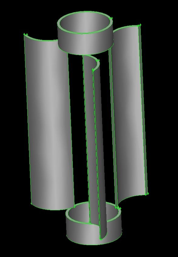
The three blades of the design are made by cutting the top and bottom from the bamboo stalk, then trisecting the remaining piece along its axis. In order to minimize air resistance on the "returning blades" (which create resistance as they move towards the wind), the connections of the blades to the hub were made to pivot. The pivot range extended between the fully open position wherein wind capture was maximized and the fully closed position wherein the blades folded into the hub, decreasing air resistance. Proper construction of the pivots ensured that the blades did not move past the fully open position.
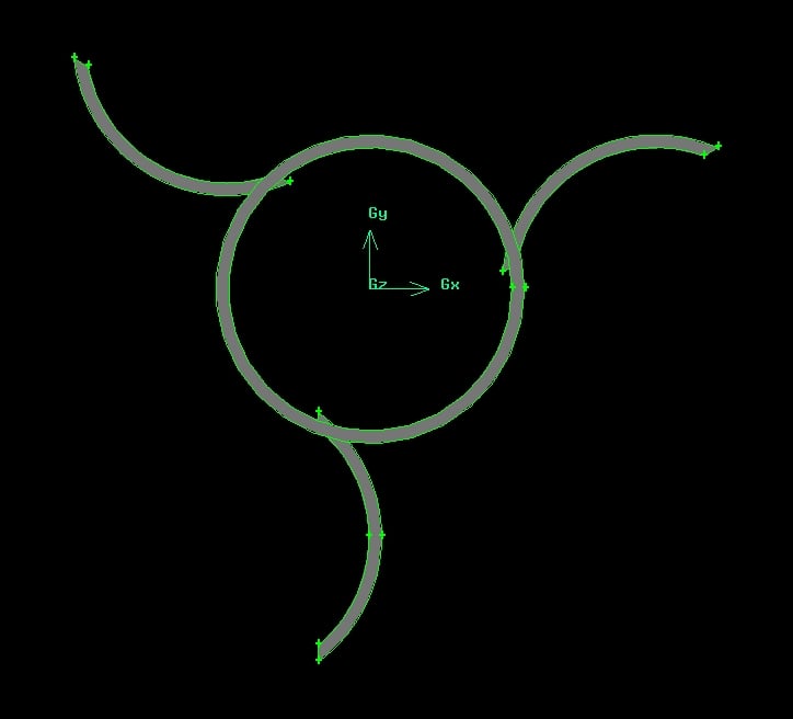
The blades were made to extend so that in the fully open position, wind capture was maximized. As such, the line from the pivot to the tip of the blade extended straight out from the hub as shown in Figure 3.
Materials Use[edit | edit source]
While materials use and specifics of construction are left to the craftsperson or further work in this area, suggestions are as follows:
- Large culm (stalk) of giant bamboo, approximately 0.3 m in diameter and 1-2 m tall.
When not available, other woods or fibres with sufficient strength (cannot be bent by human arms) are acceptable
- Saw or similar device for cutting: note that precision cutting is required, so a hatchet or axe will not work
In addition to these materials, a water pump with rotational drive (as outlined above) or electric generator must be attached to the bottom of the turbine. As this analysis only extends to blade improvement, the craftsperson will need to define and size their pump appropriately.
Proof of Concept[edit | edit source]
A proof of concept was created to show that pivoting blades worked in practice as well as theory. The device was constructed out of a pop can and coat hanger, and featured three pivoting blades. The full device is shown in Figure 4 below:
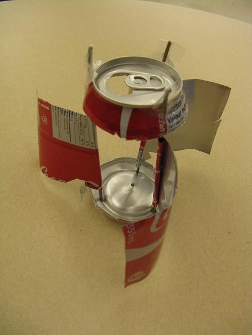
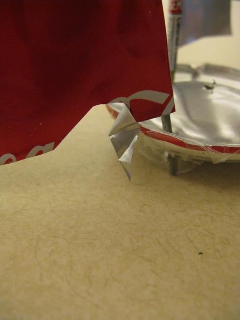
It is important to note that blades were prevented from pivoting forward through use of extended pieces of the can. In a full-scale design, small blocks of bamboo or proper pivot attachment could have the same effect. Figure 5 shows the can extensions in detail.
A brief video showing operation of the rotor is also available online.
Computational Fluid Dynamics Analysis[edit | edit source]
Computational Fluid Dynamics (CFD) analysis was used to determine extra power created by the new blade system, flow patterns around the blades, and possible improvements to the design. In order to begin the analysis, a solid model was constructed as shown in Figures 2 and 3. A mesh was created using size functions on vertices and short faces in order to show the most accurate analysis in the areas with turbulent or complex flow. This mesh is shown in Figure 6 below.
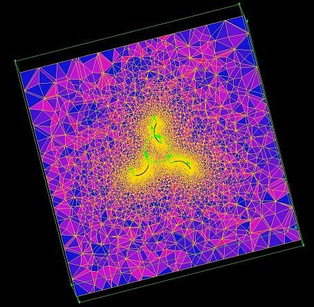
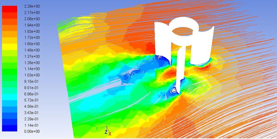
Note the increased density of the mesh around the edges of the design, especially the vertices. This analysis was conducted for two separate cases: one with a traditional VAWT design, and another with pivoting blades. Four analyses were then conducted on each case. The first analysis compared velocity pathlines, which show both the speed and direction of fluid particles as they pass both rotors. In the images below, the wind is flowing from the right of the images. In the modified design to the right, the pivoting blade has been folded back in line with the wind.
 |
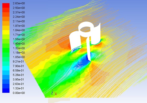 |
- All colours denote velocities given in m/s
As seen above, the pivot design offers two primary advantages. First, resistance on the returning blade decreased substantially, as can be noted by the absence of the large swath of low-velocity (blue) air behind the blade in Figure 7b. Second, because flow is not slowed by the returning blade, the blade capturing wind energy faces higher average wind velocities. This leads to increased power generation from this blade.
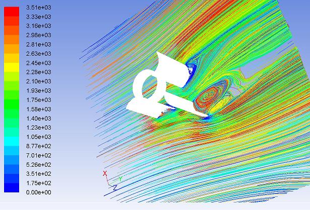
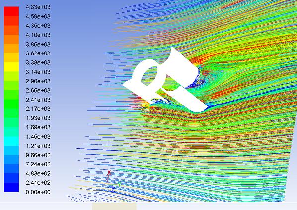
The second analysis conducted shows the pathlines of fluid particles once again, but allows for further understanding of the flow around the blades. Fluid pathlines show recirculation zones behind each blade. In general, these zones denote areas of lower pressure, which means increased drag on the blade that forms them. A comparison of the traditional rotor to the modified rotor is given in Figure 8, where wind flows from the left.
 |
 |
The third analysis conducted directly shows pressure distributions around each of the blades. The force at any point on the blade is given as:
where:
- F is the force created,
- P_f is the pressure on the front of the blade,
- P_b is the pressure on the back of the blade,
- A is the area.
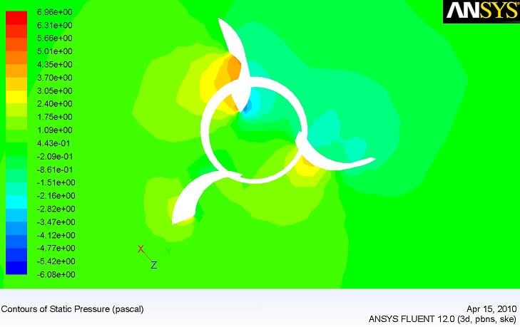
Because the difference in pressure between the front and back of the blade is proportional to the force produced (and therefore the torque), pressure difference must be maximized. The third analysis conducted shows the pressure distributions on both the traditional and the modified turbine design. Figure 9 demonstrates the results.
 |
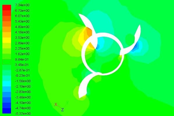 |
- All colours denote pressures in kilopascals
As seen above, increased pressure differences between the front and back of the capturing blade in the modified model combine with decreased pressure differences on the returning blade to increase power created by the blade. This pressure difference creates a force at each point on the blade, but this force is only relevant to a discussion of turbine power when expressed as a torque. Torque is given by the equation:
where
- τ is the torque produced,
- r is the distance from the centre of the turbine to the point at which the force is applied
- F is the force caused by the pressure difference,
- × denotes a cross product operation
The fourth analysis therefore used area integrals over the surface of the turbine blades and hub to find torque produced by each blade design. In the conditions used, the moment on the traditional blade was 0.081 Nm and the torque on the modified blade was 0.191 Nm. The doubling of torque was due to the two factors mentioned above: both decreased resistance on the returning blade, and increased power transfer to the capturing blade.
Improvements can be made, as the gambit mesh is available here while Fluent cases are available here and here.
Economic Analysis[edit | edit source]
The economics of this design vary greatly between Southern Asian locales: therefore, an analysis was conducted both for prices in North America and for estimated values based on average prices in India. Bamboo is considered to be available locally for negligible prices. Note that this analysis covers only components modified within the scope of this project.
| Material | Approximate Cost ($ CA) | Approximate Cost in Southern Asia (USD) | |||
|---|---|---|---|---|---|
| Bamboo | $109.00[10] | $0.00 | |||
| Labour (10 hours at average wage) | $184.08[11] | - | Saw or similar device | $24.99[12] | No Data Available, assumed to be $2 for day's rental |
| Total | $318.07 | $16.01 |
The price of $16.01 is considered to be reasonable where per capita incomes are approximately $5-$20. However, this remains a significant capital investment when time for siting, pump construction, and other aspects of irrigation and drinking water treatment are taken into account.
Societal Impact[edit | edit source]
In considering the appropriateness of this technology, it is important to be cognisant of the role of bamboo, especially giant bamboo, in the cultures in which this technology is implemented. While broad cultural generalizations cannot be drawn across the entire natural range of bamboo, one can note that it symbolizes friendship or longevity in some cultures.[13] Bamboo can also have religious connotations. It is therefore extremely important to be aware of local cultures and sensitivities before implementing any technology that uses this resource.
As mentioned above, bamboo is frequently used in construction in many Southern Asian countries, as well as across much of its natural range. It is not generally protected by environmental legislation, except for where its harvest threatens panda bears.[14] However, if harvested in a sustainable manner with regards to local laws and customs, direct societal damage due to wind rotors can be minimized.
Conclusions[edit | edit source]
Improved vertical axis wind turbine blade design can increase torque from wind turbines by a factor of 2.35, allowing for significant increases in power extraction from the wind. This increase in power can be used to pump water farther, or to increase the depth from which wind turbines can extract water: both of these outcomes have the potential to help alleviate the lack of access to safe water in developing nations. This analysis was conducted by designing a wind turbine blade that incorporated a pivot in order to decrease drag on blades that were not being used to generate power. The analysis found that increases in power came not only from decreased drag on returning blades, but also increased flow past power-generating blades.
References[edit | edit source]
- ↑ T. Ackermann, L. Söder, "Wind energy technology and current status: a review", Renewable and Sustainable Energy Reviews, Volume 4, Issue 4, December 2000, Pages 315-374
- ↑ M.W.Rosegrant, X. Cai, S.A. Cline, "World Water and Food to 2025: Dealing with Scarcity", International Food Policy Research Institute and International Water Management Institute, 2002
- ↑ "Progress on Drinking Water and Sanitation: 2010 Update", World Health Organization and UNICEF, Available: http://whqlibdoc.who.int/publications/2010/9789241563956_eng_full_text.pdf
- ↑ 4.0 4.1 A. van Vilsteren, "Aspects of Irrigation with Windmills", January 1981. Strichting TOOL Amsterdam.
- ↑ 5.0 5.1 5.2 "How to Construct a Cheap Wind Machine for Pumping Water", Brace Research Institute. Ste. Anne de Bellevue: Brace Research Institute, 1973
- ↑ "Water for life: Making it happen", World Health Organization, Available: http://www.who.int/water_sanitation_health/waterforlife.pdf
- ↑ P.T. Anastas, J.B. Zimmerman, "Design through the Twelve Principles of Green Engineering", Env. Sci. and Tech., 37, 5, 94A-101A, 2003.
- ↑ Y. Xiao, M. Inque, S.K. Paudel, "Modern Bamboo Structures", CRC Press 2008.
- ↑ 9.0 9.1 S. M. S. D. RAMANAYAKE, K. YAKANDAWALA, "Incidence of Flowering, Death and Phenology of Development in the Giant Bamboo (Dendrocalamus giganteusWall. ex Munro)", Ann Bot 82: 779-785, 1998.
- ↑ "Bamboo Price List", Canada's Bamboo World, 2003
- ↑ 11.0 11.1 "Per capita income report for Selected Countries", International Monetary Fund, 2009, available here
- ↑ Mastercraft Maximum Hand Saw: Product #57-7458-6, Canadian Tire 2009
- ↑ A.K-L. Chan, G.K. Clancey, H-C. Loy, International Conference on the History of Science in East Asia 2002, Historical perspectives on East Asian science, technology and medicine Singapore University Press.
- ↑ Earth's Endangered Species: Giant Panda Facts, Earth's Endangered Creatures, Available: http://www.earthsendangered.com/profile.asp?mp=1&ID=3&sp=321