Western University's Free Appropriate Sustainability Technology (FAST) Research GroupWanted! Students to make a distributed future with solar-powered open-source 3-D printing and recycling. Contact Dr. Joshua Pearce - Apply here
1. Establishing a connection between the Gigabot and your computer[edit | edit source]
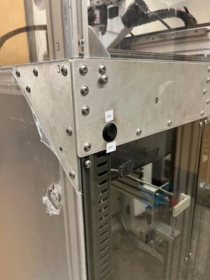
Turn on the machine with the ON/OFF button situated on the side of the right-front of the machine.
Plug the Ethernet cable into a computer. Note: If your computer lacks an Ethernet port, you'll need a USB or USB-C connector. Note: In this case, Windows 11 is used for this example, but the guidelines are similar for other versions (like Windows 10).
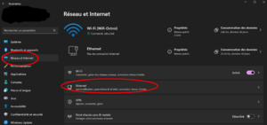
Go to Settings > Network & Internet > Ethernet.
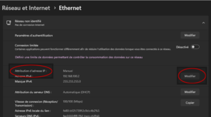
Select «IP Address assignment» > Edit.
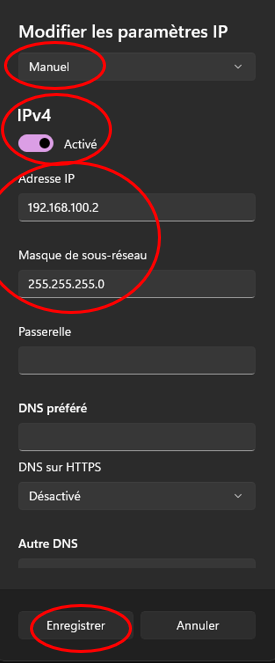
Change «Automatic» to «Manual
Activate IPv4.
Add the printer’s IP address: 192.168.100.2
Add the network mask: 255.255.255.0
Save settings.
Go on a Web browser (Chrome, Opera, Firefox…) and type this address in the tab bar: 192.168.100.8
2. Web Interface or Duet Web Control (DWC)[edit | edit source]
1
Menu
Menu with the dashboard and configs.
2
Status
Printer state: Idle/Busy, Toolhead’s position, Extruders movements, Extruders’ motor speeds, and Sensors’ measures.
3
Tools
Heating Temperature control of three heaters and bed: Target temperatures, measures, active or standby states.
Tool Activation
4
Temperatures
Temperature chart: shows the temperature curves of the heaters and bed temperature over time.
5
Printer head movement
Commands to change the head position. Can move it manually or get it at its reference (Home).
Note:
To move the Head, first we must put it to its origin (X = 0, Y = 754, Z = 5) with the button Home All (or Home [axis] to put it back to origin for one axis only).
Note that the Y axis starts with negative values from its reference.
Note that Z axis only home if X and Y are home.
6
Extrusion
Commands to change the extruding speed, which extruder to activate and extrude/retract the material.
Note: Extrusion control allows to choose which extruder’s screws we want to turn (crammer (E0), Extruder (E1), or both ( Mix) ) buttons, and at which speed we want with the “feed/feed rate” buttons.
7
Macros
G-Code programs to execute tasks. To execute repetitive or automated tasks, we can program them on macro files in G-code language, in the interface’s “Macro” tab. After being saved, click on it to make the printer execute the task. To edit a macro, right click on it and Edit File.
Current Macros:
Allow cond extrude: This enables extrusion at temperatures below 160°C. Note that it is not recommended for prolonged use when material is present. It is primarily designed for testing motor movement without waiting for the temperature to reach the minimum required level.
BL-Touch: Perform a rapid check on the BL-Touch (deploy/retract) with this.
Disable all stepper motors: Stop the idle hold on all axis and extruder. Be aware that by disabling idle hold during printing, you will get quality issues.
Purge: Allows for material purging.
Set Position: Allows manual specification of the axis positions by setting the current user position to the values given.
Mesh bed probe: Uses a probe (BL-Touch in our case) to measure the bed height to determine its tilt and overall flatness.
You can also control the machine using the screen located at the back-left of the machine.
1
Menu
Main Control Menu for the Machine.
2
Stop or Emergency stop
To deactivate and stop the machine immediately, press this button.
3
Bed Temperature activation
To activate the heating of the bed, press this button.
4
Temperatures activation
Press this button to activate the extruder heaters for heating and tool activation.
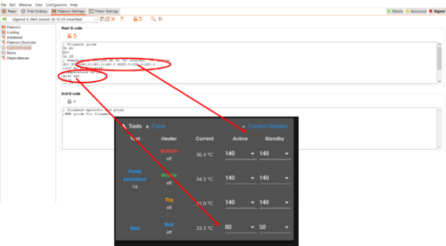
5
Temperatures
Heating Temperature control of three heaters: Current, active, and standby states.
Note: To set the temperatures, click on the active button corresponding to each temperature. A new small window will open (refer to Fig.Set_temperatures), then adjust the temperature by pressing +5 or +1. Once you reach the desired temperature, click 'Set.
6
Printer head position and homing
Displays the current position of the axis and provides homing buttons for both individual and all axes.
7
SDCard
Offers a button for accessing G-codes stored on the SDcard.
8
Printer head movement
Commands to change the head position. Can move it manually. A new window will open, displaying the same information as shown in the Duet Web Control.
Note:
To move the Head, first we must put it to its origin (X = 0, Y = 754, Z = 5) with the button Home All (or Home [axis] to put it back to origin for one axis only).
Note that the Y axis starts with negative values from its reference.
Note that Z axis only home if X and Y are home.
9
Extrusion
Commands to change the extruding speed, which extruder to activate and extrude/retract the material. A new window will open, displaying the same information as shown in the Duet Web Control.
10
Macros
G-Code programs to execute tasks. To execute repetitive or automated tasks, we can program them on macro files in G-code language, in the interface’s “Macro” tab. After being saved, click on it to make the printer execute the task. A new window will open, displaying the macros.
11
Control
Press this button to return to the menu.
12
Status
A new window will open and displays the current printing information. Refer to Fig. Status_window
13
Console
A new window will open, showing the current machine status, and a keyword icon will appear in the right corner, enabling you to send direct commands through G-code.
Press this button to control the speed percentage. This allows manual control of the speed, allowing you to go slower or faster
2
Cooling fans control
Press this button to control the cooling percentage. A new small window will open (refer to Fig. Set_temperatures), allowing you to adjust the desired cooling percentage by pressing +5 or +1. Once the desired setting is reached, click 'Set.
3
Baby steps
This command tells the printer to apply the specified additional offset to the Z coordinate for all future moves and to apply the offset to moves that have already been queued if this can be done.
4
Pause/ Resume / Cancel printing
This command enables to temporarily pause the current printing process, providing options to resume or cancel it as needed.
Note:When pausing printing from the screen, if you choose to resume, it will automatically stop the entire printing process. For pausing and resume the printing, connect to the DWC. Apologies for this inconvenience.
In order to ensure optimal performance during printing, the printer bed has undergone calibration. It is recommended that, for your printing processes, the adjustment of additional offset to the Z-axis should be made using the baby steps feature. However, recalibration is advised only in cases where the gap for the baby steps exceeds 1mm. Please follow the outlined steps below for recalibrating the bed:
Using a clean cloth, wipe the build plate and the nozzle.
Turn on the machine.
Home all axes.
Heat the nozzle to 220°C.
Heat the bed to a temperature range of 60-70°C.
Lower the bed by 30mm.
Position the printing head in the middle of the bed (X=300, Y=345).
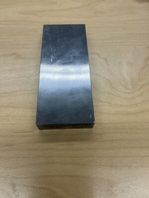
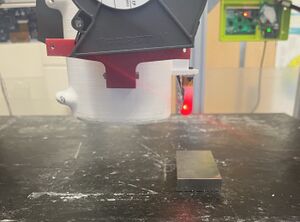
Place the 10-millimeter bar (refer to the figure.Calibration bar) under the BLTouch sensor (fig.Calibration bar under the BLtouch ). make sure the bar DOES NOT touch the nozzle. Calibration barCalibration bar under the BLTouch
Press the home Z button.
Remove the bar.
Move the bed to 0 (in the DWC dashboard or screen panel, press Z=-25 (DWC) or -50 (screen panel)).
Insert the bar beneath the nozzle. If the bar passes under the nozzle, and the gap is too narrow (refer to the figure), follow these steps:
Narrow
a. Utilize feeler gauges to measure the gap between the bar and the nozzle.
b. Navigate to DWC > System > config.g.
c. Within the configuration, locate G31 (Ctrl + F > type G31). If you can't locate G31 by using Ctrl + F, simply scroll down until you come across this specific code.
d. Under G31 in the Z section, increase the numerical value based on the measured gap (example: if the current value is 2.5 and the measured gap is 0.5, the new value should be 3). NOTE: IIf you don't have a gauge, please increment by 0.2 gradually until you reach the desired point.
e. Save the configuration. A window will appear, asking, "Reset board?" Press "yes."
f. After the machine restarts, use the macro "set position" to maintain the current position of the printing head.
g. Lower the bed 25mm. Repeat steps from #6 to #e until the bar makes contact with the nozzle, and no gap exists between them (refer to the figure Perfect calibration).
Perfect calibration
Otherwise, if the bar does not pass under the nozzle (refer to the figure lower nozzle), follow these steps:
Lower nozzle
a. Navigate to DWC > System > config.g.
c. In the configuration, locate G31 (Ctrl + F > type G31).
d. Under G31 in the Z section, decrease the numerical value based on the measured gap (example: if the current value is 2.5, reduce it by 0.2, so the new value should be 2.3). If you don't have a gauge, please increment by 0.2 gradually until you reach the desired poin
e. Save the configuration. A window will appear, prompting a reboot of the machine; press the "yes" button.
f. After the machine restarts, use the macro "set position" to maintain the current position of the printing head.
g. Lower the bed 25mm . Repeat the steps from #8 to #e until the bar makes contact with the nozzle, and no gap exists between them (refer to the figure perfect calibration).
13. Home using G28.
14. Do the mesh bed probe in the console sent the code G29 "This command uses a probe (BL-Touch in our case) to measure the bed height to determine its tilt and overall flatness. It then enables mesh bed compensation so that the nozzle will remain parallel to the bed.
15. In the console sent the M500 to save the mesh probe.
After designing a part on CAD software (Onshape, Solidwords, …), use the PrusaSlcer software to prepare the part for printing. If you do not have Prusa slicer download the latest version from (https://github.com/prusa3d/PrusaSlicer/releases)
Download the Printer configuration for Prusa from https://osf.io/h7s5u/ (File name: PrusaSlicer_confin.ini)
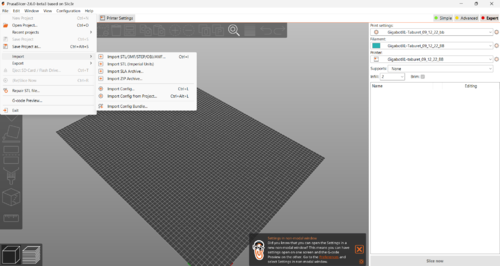
Import the config profile of the printer in the software (.ini file). For this, open the Prusa slicer go to File > Import > Import Config
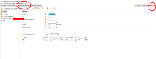
To change the type of material used in the printing process go to “Filament settings”.
To change the bed and heaters temperatures in "fillament settings" go to “Custom G-Code” on the left tabs (if it’s not visible, check “Expert” on the right to show it).
We now have access to the starter G-code. The command G10 allows to change the target temperatures of the heaters. The R part is for standby temperatures and the S part for active temperatures.The command M190 changes the bed temperature ex.M190 S50 to target it at 50°C. Note:Note that the order of the S temperatures is as follows: the first temperature corresponds to the bottom (nozzle), followed by the middle, and then the top
Import the STL file. For this, go to File > Import > Import STL/3MF/Step/obj
If material needs to be purged do as follows[edit | edit source]
Before using the material you want, we must purge the old material inside the printer’s system.
Lower the bed by approximately 100mm to facilitate material flow. Place a paper towel under the nozzle on the bed to prevent material spillage.
If there's remaining material in the crammer and feeder, have a bucket ready for recovery and unscrew the crammer's motor to empty them. Use a vacuum cleaner to remove dust and particles.
If aware of the melting temperature of the old material, set the heaters to this target temperature. Otherwise, set them to 260°C, 240°C, and 220°C.
Click on "Extrude" (#6) to ensure material flows from the nozzle or the screws are not stuck. If the screws are stuck (motor noise/cracking sounds), use "Retract" to lift the material back to the crammer for removal.
If material flows smoothly and screws are not stuck, extrude a few times while gradually increasing the feed rate. Then, activate the "Purge" macro if no issues arise.
Once the system has been purged, place purging material pellets in the crammer and execute another purge to clean the system.
If material do not needs to be purged do as follows[edit | edit source]
Clean the build plate with isopropanol and wipe with a cloth. In case of glue residue, use warm water and wipe.
2. Fill the feeder with the desired amount of material (PLA pellets, crushed plastics, etc.).
If using DWC:
In the interface, navigate to Menu > Files > Jobs. On the right, find the Upload G-code file(s).
Select the sliced G-code file.
Once loaded, click on the file name.
Confirm by clicking yes, and the printing will commence.
Note:The printhead will return to its reference position, and the printer will not start until the bed and heaters reach the target temperatures set in the slicer. Heating can take up to 30 minutes, depending on the temperature settings
Note:When printing high-temperature materials that require additional assistance for adhesion, utilize Nano Polymer adhesive. Prior to usage, refer to the safety data sheet (SDS) available at [link: https://cdn.shopify.com/s/files/1/2327/6017/files/Vision_Miner_NanoPolymer_Adhesive-V2-US_SDS-08_19_2020.pdf?v=1597940700] for information on the required personal protective equipment. Please be aware that this is a highly flammable liquid