

This tutorial was created to help everyone who wants to install a Lepton camera using a Raspberry Pi. We used the information available in many tutorials and added our own knowledge to improve them.
The device that we tested is the Raspberry Pi B + but the installation shouldn't be too different for other versions of the device .
About Lepton camera[edit | edit source]
Lepton is a complete long-wave infrared (LWIR) camera module designed to interface easily into native mobile-device interfaces and other consumer electronics. It captures infrared radiation input in its nominal response wavelength band (from 8 to 14 microns) and outputs a uniform thermal image.
Environment Specification[edit | edit source]
| Operating Temperature Range | 10° C to 65° C (-20° C to 75° C with some possible performance degradation) |
| Maximum Operating Temperature | 353.15 K (80 °C) |
| Storage Temperature | 40° C to 80° C |
| Relative Humidity | 95 % |
| Thermal Shock | Air-to-air across operating temp. extremes (-10° C to 65° C, 65° C to -10° C) |
| Vibration | Transportation profile, 4.3 grms |
Image Characteristic[edit | edit source]
| Intrascene Range | 0 K to >400 K (-273.15°C to > 126.85°C) |
| Operability: Number of non-defective pixels | >99.0% ( < 1 % defect typical ) |
Applications[edit | edit source]
- Safety and Security
- Automotive
- Micro and Nano UAV/UGV platforms
- Home Repair & Energy Efficiency
- Building Automation & Presence Detection
If you want to know more specifications about the Lepton Camera, you can go on Lepton Datasheet

Hardware[edit | edit source]
Required Materials[edit | edit source]
These are the materials that you will need to install your Lepton Camera:
- Raspberry Pi Model B+.
- A 5V power supply with a micro USB termination.
- Must be able to source at least 700mA
- It can be a phone charger, they work well. (Phone chargers work well)
- A SD Card:
- At least 8 GB and up to 32 GB of storage
- No less than class 4.
- A USB keyboard
- A mouse ( with a USB connection)
- A HDMI cable
- An Ethernet cable and a connection to an Internet-connected network.If you want to use WiFi in your Raspberry Pi, you can buy a WiFi connection adapter. This tutorial used a Mini 150Mbps USB 2.0 WiFi Antenna Wireless Network LAN Card Adapter 802.11N/G/B.WiFi connection adapter
<script type="text/javascript" src="//s7.addthis.com/js/300/addthis_widget.js#pubid=ra-5a93e87a759ecc6f"></script>
Prepare the SD Card – Formatting[edit | edit source]
First of all, we are going to format and prepare the SD card. In this section, you are going to use your computer. The first step will be formate the card and the second step will be install the NOOBS software(Your Raspberry will need it). In this tutorial we are using the OS windows. If you have another one, you can check the steps here: Different OS.Please, follow these instructions:
Formatting the card
- Go online and Download Formatter for Windows
- Unzip and extract the Download and run Setup.exe.
- When prompted with the SDFormatter InstallShield Wizard accept and install the program, then click finish.
- Next, open SD Formatter ( The program that you just installed). You should see see something like this:
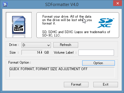
Fig 2: SDFormatter - Click Option and set FORMAT SIZE ADJUSTMENT to ON, then click OK.
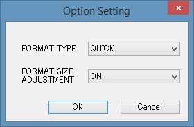
Fig 2.1 : Option Setting - Where "Drive" is listed select your card. If you are using only one card in your computer, it will be selected automatically.
- Click "format " and then click "OK" three times as it appears.
- The SD card is now formated! The next step is to install the NOOBS software.


Installing the NOOBS Software
- Visit the Raspberry Pi Downloads Page and download the most recent NOOBS (offline install) (NOOBS_v1_4_1.zip as of 2015-05-11).
- Unzip and extract the download. The extracted folder should look like this:
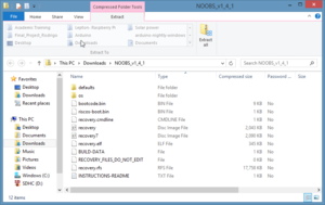
Fig 3 : Download NOOBS - Now, you need to copy the extracted folder contents onto your recently formated SD card.
- Your card now is good to go!

Connections[edit | edit source]
Be careful with the Lepton camera. It isn't particularly sensitive to electrostatic discharge, however it is a complex and relatively pricey component. A few precautions are necessary while working with it so it isn't accidentally damaged. One reliable investment is a breadboard; it provides a safe location to install the camera.
Now, we can start to build the project. Follow the steps below:
Connect the Lepton camera to the raspberry
- Use a breadboard for connections.
- The diagram in Fig. 4 has 20 GP10 (40 pines) and the Raspberry Pi has 13 GP10 (26 pines), for this project only first 26 pines are important.
- About the CS pin, if you got a red square, switch pin 26 to pin 24

Connect the monitor
- Connect a HDMI cable between the Raspberry and a display monitor. (A VGA to HDMI adapter may be necessary)
Connect mouse and keyboard via USB
Insert the prepared SD card into the raspberry
- The SD card will click into place when it is correctly connected.
Establish an internet connection
- Several software downloads are needed to utilize this project and to take full advantage of what the raspberry pi can offer. Therefore, an internet connection is quite important.
- Either an ethernet cable or a wifi adapter may be utilized. The instructions for a wifi adapter are here
Connect the power
- Lastly, do a final check on the previous connections. If they are working, connect the power supply the Raspberry. (We used a phone charger cable)
Hardware section is complete! The project should look something like this:
-
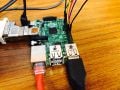
Fig 5.1: Raspberry Configuration
-
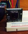
Fig 5.2: FLIR Lepton on a breadboard
-
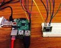
Fig 5.3: Diagram Connection


WiFi adapter[edit | edit source]
A WiFi adapter can be used to connect the Raspberry Pi to the internet. To use a WiFi adapter with the Raspberry Pi follow the instructions below:
The Raspberry Pi official website provides 3 different tutorials to install the WiFi adapter. Those instructions did not work when we tried them. Since they could work for others they can be found here.
In this tutorial we will be using the commands that worked for us.
- Connect the WiFi adapter into the Raspberry Pi.
- Open the LXT Terminal on the Raspberry Pi desktop.
Command lines in LXT Terminal
- To determine which WiFi signals are available for the Raspberry Pi enter with the following command:
sudo iwlist wlan0 scan
PS: In particular to Michigan Tech Labs, we needed to download a open source software in our own computer to share the Michigan Tech WiFi. The Open source software is the Virtual Router. You can download it in this link Virtual Router . With this software you can share the Michigan Tech WiFi with you raspberry. You just need to crate a name and a password. Take a look at the example above:

When you finish to install the sot
- All the WiFi available will be displayed. Determine the ISSD and the password of the prefered WiFi connection.
- Enter the following command:
sudo nano /etc/wpa_supplicant/wpa_supplicant.conf
- Add the code below to the file. Recall the IDSS and the Password.
network={
ssid=" Your ESSID"
psk="Your_wifi_password"
}
- Here is an example:
network={
ssid="WiFi-Test "
psk="12345678"
}
- When finished, use Ctrl + X, chose Y, and press Enter. (It will save the changes made)
- To activate changes use:
sudo ifdown wlan0
- Then enter:
sudo ifup wlan0
- Confirm the WiFi is working using the following command:
iwconfig
- The Wlan0 will be connected in the WiFi that you have chosen.
Software[edit | edit source]
The software installation allows use of the Raspberry Pi.
Raspbian[edit | edit source]
Raspbian is a free operating system based on Debian optimized for the Raspberry Pi hardware. It is the ideal operating system for the Raspberry Pi
- There may be a delay between the Raspberry signal and monitor display, this is normal. Fig. 7 shows the displayed screen.
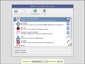
Fig 6 : Raspbian Installation - Click the first option ( Raspberry RECOMMENDED).
- Click "Install". It will take about 30 minutes to install.

After this part your Raspberry Pi is ready for use
FLIR Lepton thermal camera software[edit | edit source]
When the installation of Raspbian is finished, it is time to install the FLIR Lepton thermal camera software. We are using Pure Engineering code to run the Lepton
- Now, you need to open the LXTerminal, where you will type your commands. Click in the icon showed in the picture below:

- When it is done, you need to enter the command below. It will open the configuration section for you.
sudo raspi-config
- You will see this windows:
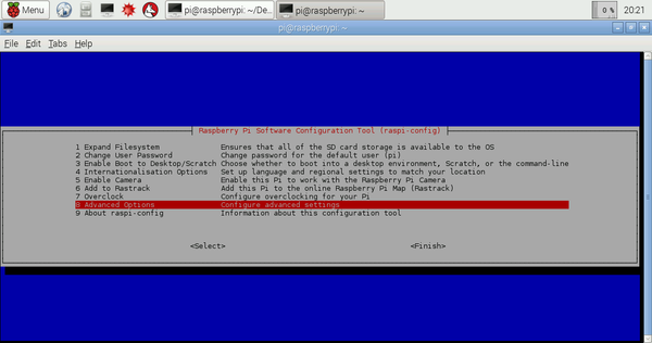
Fig 8 : Configuration Windows - Go to "Advanced Options".
- You need to activate the "SPI". For this, follow the instructions below:
- Select SPI
- You need to enable the SPI interface: click "YES"
- Click in "OK"


- You need that your SPI Kernel Module to be loaded by default, therefore click "YES" .
- Click in "OK"


- After this, do the same to I2C.
- Now, select finish at the end of figure 8 and reboot the raspberry pi you will be asked if you want to reboot your Raspberry Pi. Do it.
- Now, it is time to use the internet connection. You need to download the QT application( example codes from Pure Engineering). Therefore, make sure that you have a good internet connection.
- For the next steps, enter the following command:
sudo apt-get install qt4-dev-tools
- After this, you will be asked to enter with "y" or "n". Enter "y".
- Now go to the internet icon and this website: https://github.com/PureEngineering/LeptonModule
- When you open the website, click in "Download ZIP" (it is in the right side of your screen).
- Move your downloaded folder to the pi directory.
- Now unzip the zipped folder. Use the command:
unzip LeptonModule-master.zip
- Now change the current directory to the folder "raspberrypi_video" that is in the "LeptonModule-master" folder. Do that using the command:
cd /home/pi/LeptonModule-master/raspberrypi_video
- Now, you need to cd into the "LeptonSDKEmb32PUB" directory and run "make":
cd /home/pi/LeptonModule-master/raspberrypi_video/leptonSDKEmb32PUB
make
- After this, cd back to the "raspberrypi_video" directory:
cd /home/pi/LeptonModule-master/raspberrypi_video
- Now, run:
qmake && make
- Your thermal camera is ready for use! To get it to work, run:
sudo ./raspberrypi_video
Changes and Erros[edit | edit source]
Video size[edit | edit source]
It is possible to change the video size:
- Open the main.cpp file. It is located in the "raspberrypi_video" folder
- The part of the code showed in the picture below defines the size and position of the video window. The numbers in the red box define where the window will appear in your screen and the numbers in the green box define what size that window will have.
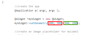
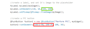
- You will also need to change the size of the image that is sent to the placeholder window and the position of the "Perform FFC" button.
- To save your changes go to the left top side of the page press "file" and click in "Save"
- After you finish, go to the LXTerminal, cd to the "raspberrypi_video" folder and run "qmake && make"
- Your changes were saved, run the program and check if that is what you wanted. If you don't like the resolutions you can change it back or change it to another size


Perform FFC
We experienced an error when pressing the "Perform FFC" button. If you experience the same error you can follow the instructions below:
- Go to LXterminal and execute the following command:
sudo nano /etc/modules
- Go to the last line and write: "i2c-dev"
- Press "ctrl o"
- Press Enter
- Reboot the system. The FFC should be working now
- In case you experience other errors you can try to find the solution here: https://groups.google.com/forum/#!forum/flir-lepton
Recording Video[edit | edit source]
The current best way to record the video produced by the FLIR Lepton camera is to connect the raspberry to a PC or laptop. That is easily achievable using VNC (Virtual Network Computing). VNC allows a user to remotely control the desktop interface of another computer. Other advantages of using VNC with Raspberry are:
- There are many open source screen recorder programs
- It will allow the user to control the raspberry using linux or windows system
- The recorded files will be saved in the user's computer, therefore, it won't be necessary to store it in the Raspberry memory card
- It won't be necessary to attach a monitor, keyboard and mouse to the Raspberry
- Using VNC we can easily carry the thermal camera system
VNC connection
To set up a VNC is easy. You will need to set up both the raspberry and the computer that you will be using to remotely control your raspberry.
Setting up the Raspberry Pi
- Go to the LXTerminal and install the Tight VNC Package
sudo apt-get install tightvncserver
- Run the TightVNC Server
tightvncserver
- The server will require you to enter a password. The password needs to have more than 4 and less than 9 characters
- The LXTerminal doesn't allow you to see the password you are typing. Just type it and press enter.
- Start a VNC session
vncserver :1 -geometry 1920x1080 -depth 24
- The ":1" represents the number of the VNC session (you can have more than one VNC sessions)
- It is possible to change the resolution of the screen. In this example we are using full HD resolution (1920x1080)
- If you wish to set up a VNC session from the start up, follow the instructions on the elinux.org website
- If you want to end a VNC session, use the command:
vncserver -kill :display
- ":display" is the number of the VNC session
Setting up your computer
- In the last step of setting uo your computer you will need the IP address of your Raspberry Pi. If you don't know the ip adress of your Raspberry Pi, execute the following command on the LXTerminal:
ip addr show
- The IP address is the number in the blue box

Windows
Follow the instructions for your Windows based computer on the Raspberry.org: Windows website.
Linux
Follow the instructions for your Linux based computer on the Raspberry.org: Linux website.
Mac OS
Follow the instructions for your Mac OS based computer on the Raspberry.org: Mac OS website.
Screen recorder software
You will need a screen recorder software to capture the video that the Lepton Thermal camera is sending to your computer. You can use whichever program you want. We are listing some open source software options.
Windows
We downloaded and tested ShareX. ShareX is an open source software that allows screen recording, printing screen and has many OTHER tools. You can download the software for free at getsharex.com
Linux
Mac OS
Recording video on the Raspberry[edit | edit source]
This is a work in progress
Install ffmpeg from source. This step is very important. It won't work with the Raspbian version of ffmpeg because the Debian version of libavcodec doesn't contain the H264 libraries needed for the flash streaming protocol.(From the Raspberry Forum)
sudo aptitude remove ffmpeg
cd /usr/src
sudo mkdir ffmpeg
sudo chown `whoami`:users ffmpeg
git clone git://source.ffmpeg.org/ffmpeg.git ffmpeg
cd ffmpeg
./configure
make
sudo make install
- Running ffmpeg
ffmpeg -f x11grab -s 1024x768 -r 25 -i :0.0+250,150 /tmp/out.avi
This will grab the image from desktop, starting with the upper-left corner at (x=250, y=150) with the width and height of 1024x768. In this example the video is being saved in a temporary folder, you can save it in another folder. "out.avi" is in the format "filename.fileformat".
You can find more information about ffmpeg here and in the ffmpeg.org website.
Our Application[edit | edit source]
You can implement the code from the Pure Engineering and create new applications for your Lepton camera . There is good file from FLIR which has functions and instruction that will be helpful for news applications. You already downloaded this file in previous steps. To find it, follow this steps:
- Go to the Pi directory and open "LeptonModule-master"
- Open the folder "raspberrypi_video"
- The file that you are looking for is "lepton_interface_design_document.pdf"
Using this file, we created some applications. You can check them below.
Get the Internal Temperature of the camera[edit | edit source]
With this applications, we are able to see what is the camera internal temperature. It can be very helpful for future applications because there is a relationship between the output from the camera and its internal temperature. We will describe below what we did:
- Go to the "Pi directory"
- Open the "LeptonModule-master"
- Open the "raspberrypi_video"
- Open the file "Lepton_I2C.cpp"
- In this file, you will declare the function witch will get the Internal temperature:
- First of all, you need add these line of code below "#include "leptonSDKEmb32PUB/LEPTON_Types.h""
#include "leptonSDKEmb32PUB/LEPTON_AGC.h"
- Now, add this line of code below "LEP_CAMERA_PORT_DESC_T _port;"
LEP_SYS_FPA_TEMPERATURE_KELVIN_T fpa_temp_kelvin;
LEP_RESULT result;
- Now, you will declare the function. Go to the end of this file and add the function:
int lepton_temperature() {
if(!_connected) {
lepton_connect();
}
result = ((LEP_GetSysFpaTemperatureKelvin(&_port, &fpa_temp_kelvin)));
return ( fpa_temp_kelvin);
}
- You need to save what you typed. Go to the files and save it.
- Go back to the "raspberry_video " and open "Lepton_I2C.h"
- you need to add this line of code below the " void lepton_perform_ffc();"
int lepton_temperature();
- Now, we have the function lepton_temperature() that can return you the internal temperature of the camera. If you want to use this value for any calculation, you just need to declare a variable , and match with this function that you created.
Temperature scale[edit | edit source]
The Lepton camera uses the internal temperature as a parameter. The output frame for the internal temperature is 8192. If the range of the temperature is not too big, the whole output range will follow an almost linear relationship with this point ( Internal Temperature, 8192).
Get the maximum and minimum temperature
With that information we are able to get an approximated temperature from any output. In order to do that we took an experimental point ( Temperature and output) using the hot plate available in the Michigan Tech Lab. After this, we did a linear equation using two points : ( Internal Temp , 8192) and ( Experimental Temperature , Experimental Output ) . You can see the equation below:
Temperature( Kelvin) = (8192 - (Internal Temperature * ( (Experimental Frame- 8192 )/ ( Experimental Temperature - Internal Temperature )))
If you analyse the original code in the file "Lepton Thread.h", you can see that you are able to take the maximum and minimum output frame. Therefore , if you use the Maximum and Minimum output on the equation above, you can find the Maximum and Minimum temperature.
Color and Frame relationship
if you take a look at the original code at the file "Lepton Thread.h", you can realize some important points :
- The code gives the maximum and minimum output frame.
- The variable "value " gives the relationship with the color.
- Value has a range of 0 < Value < 255.
- The maximum frame represent Value = 255.
- The minimum value represent Value = 0.
Therefore, using the linearity and the last two points ( MaxFrame , Value = 255) and ( MinFrame , Value = 0), we can find the relationship between the frame and the color :
Value = ((-255*Frme) + ( 255 * MinFrame)) / (MinFrame - MaxFrame)
Frame and Temperature Relationship
we can realize that:
- The maximum frame is related with the maximum temperature.
- The minimum frame is related with the minimum temperature.
Using these two points above and the linearity we can find the relationship between frame and temperature.
- FrameMax --> TempMax
- FrameMin --> TempMin
Frame = ((FrameMax - FrameMin) / ( TempMax - TempMin)) * (Temperature - TempMax) + FrameMax
Setting up a range to the output frame[edit | edit source]
We can limited the range of the output form the Lepton camera. Therefore, if you want to see just a small range of temperature , we are able to do that. You need to follow the steps below.
- Go to the file "LeptonThread.cpp"
- Looking for the lines nof the code where they get the maxValue and minValue. (It is inside the loop "for ( int i = 0 : i < FRAME_SIZE_UNIT!; i++)"
- After the lines that we told above, you will set up your output. See the example : .
maxValue = 1264;
minValue = 8000;
- After set up the output valor, add the condition below: (it needs to inside the the same loop "for ( int i = 0 : i < FRAME_SIZE_UNIT!; i++)")
if ( frameBuffer[i] < minValue) {
frameBuffer[i] = minValue;
}
if ( frameBuffer[i] > maxValue) {
frameBuffer[i] = minValue;
}