How to Build a Mechanically Powered Battery Charger for LED Lighting
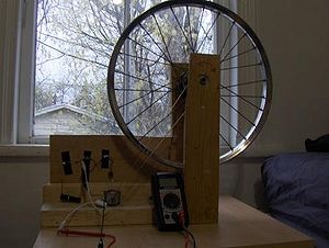
The purpose of this Mech425 project is to design a mechanically powered (Human powered) battery charger that will recharge low voltage batteries used for LED lighting. The reason it charges low voltage batteries is because a LED does not require much voltage to produce light. The lower the rated voltage of the battery that has to be recharged, the less work the human has to do in order to recharge it. The design should be efficient and cost effective to provide a means of charging batteries to those who may not be able to afford electricityW and or those who are in areas where electricity is unavailable. The design should also be made of materials that are easily available.
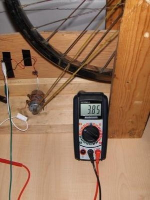
This design utilizes materials that are scavenged from other applications. The proposed design is constructed from an old bicycle rim that is connected to a DC motor from an old printer via a belt that comes from the same printer. When the rim is manually spun it will cause the motor to produce an electric current which is needed to charge a battery. The proposed design is human driven but the overall design could be altered to use a source of power such as the wind to spin the motor, alleviating the need for a human to spin the motor.
Introduction and Theory[edit | edit source]
This section is intended to give some insight into the technical background of the project to help understand the overall design.
A batteryW is a device that converts stored chemical energy into electrical energy, and is a source of direct currentW.[1] The applications for a battery are endless, but for the purpose of this project they will be theoretically used as a power source for LED lighting. There are two broad categories of batteries: primary and secondary. Primary batteries are not rechargeable; once the chemical energy in the cell is depleted it cannot be restored by electrical means. Secondary batteries can be recharged by applying electrical energy into the cell.[2]
A battery chargerW is a device used to put energy into a rechargeable (secondary) battery by forcing an electric current through it.[3] A mechanically powered battery charger uses human power to generate the electricity needed to create the necessary electric current to charge the battery.
Rotating Electric Machines[edit | edit source]
There are three basic classifications of rotating electric machines: Direct-current Machines, Synchronous machines and Induction machines.[4] If a machine converts mechanical energy into electrical energy then the machine is acting as a generator. If the machine converts electrical energy into mechanical energy then the machine is acting as a motor. There are similarities with respect to all rotating electric machines in that the two main components are a stator and a rotor. The rotor rotates inside the stator and is separated by an air gap. The rotor and stator each have a magnetic core and windings to produce a magnetic fluxW (or the stator is a permanent magnet as is the case in the DC motor used in this project). The rotor is fastened upon a bearing-supported surface and is either connected to a prime mover (if the rotating electric machine is a generator) or to a mechanical load (if the rotating electrical machine is a motor).[4]The rotor is attached by means of chains, pulleys, belts etc. The speed of the motor is determined by the applied voltageW and the torque of the motor is related to the electric currentW.[4]
Producing Electricity with a DC Motor[edit | edit source]
A DC motor is generally used in applications that require accurate speed control.[4]The motor is connected to a power supply which provides electrical current to the windings (coilsW) in the rotor. When a current is passed through windings, a magnetic field is produced. This magnetic field causes the rotor to spin therefore creating useful mechanical work. These windings may also be used to induce a voltage if the reverse action is taken (rotor is manually spun and the DC motor acts as a generator). This can be explained by Faraday's Law of InductionW which in short states that a voltage is induced by a changing magnetic field.[4]The presence of the magnetic fields makes it possible to produce an electric current and generate power.
A magnet also produces a magnetic field where the strength is quantified by:
Magnetic flux ϕ and magnetic flux density B, units of weber (Wb) and tesla (T) repectively, where: and [4]A magnetic field is generally represented by lines, and the strength of the magnet can be visualized by analyzing the density of these lines. By definition the magnetic field lines travel from north to south.[4]
Charging a Battery[edit | edit source]
The motor must be able to produce enough voltage to charge the battery. For example if the rated voltage of the battery is 5 V then the motor must be able to produce at least 5 V. It also must be able to generate enough current so that the time required to charge the battery is lowered. The larger the amperage the shorter time will be required to recharge the battery. Rechargeable battery capacity is rated in mAh (milliampere-hours). The total capacity of a battery is defined as "C", that is it can supply C mA for 1 hour, or 2C for 30 minutes etc.[5] The rate of charge is determined by how much electrical current is allowed into the battery by the battery recharger.[6]The charge current depends upon the technology and capacity of the battery being charged.[3]As a general rule, to arrive at an appropraite charge rate, the capacity of the batter should be divided by 10 (this is called the C/10 rate). There are however charge rates as high as C/3, but this charge rate will only be maintained for a short period of time.[7]Therefore the fastest amount of time that a battery can be recharged is 3 hours but the recommended charge rate should be used. To find the recommended charge rate of the battery one should contact the battery manufacturer.
A battery rated at 150 mAh (the one used in this design) can theoretically sustain a 15 mA discharge current for 10 hours (150 mAh/ 15 mA). Some LEDs have a maximum rated amperage of 15 mA.
However it is very important to note that the battery is not overcharged, nor should it be charged at a rate that the battery cannot handle. If the battery is overcharged it may explode. It is important to understand all of the parameters involved in charging a battery before constructing a battery charger. It is also important to note that no battery will last forever as they wear out and will eventually need to be replaced,[7] however rechargeable batteries are a great way to reduce cost and waste.[6] One downside to batteries is that when they do need to be replaced they contain toxic materials and should be disposed of properly.[7]To avoid shortening the life of a battery considerably, the battery should not be completely discharged before being recharged.[6]=The Prototype=
The performance of the prototype and a discussion is included in this section. The parts, tools and steps required to construct the prototype design are also included.
Performance and Discussion[edit | edit source]
The final prototype works although there are many improvements to be made on the design. The most notable design change would be to have a better system to spin the rim, ideally one that was not human powered. The design consists of a wheel that is rotated by hand that is connected to a DC motor. The motor is connected to the battery and when the wheel spins it provides electricity to the charge battery. The battery chosen was a 4.8V 150mAh battery that was turned into a 3.6V 150mAh battery. This means the fastest possible charge rate is 50mAh based on the C/3 rate or lower depending on what charge rate is chosen. To be safe the battery will be aimed to be charged at C/5 (which means it would take 5 hours to charge this battery). Some testing done on the prototype was done and the data shown in table 1 shows the results. The amount of current and voltage through the circuit is proportional to the rotating speed of the rim. The motor easily puts out the required amount of voltage needed to charge the battery and exceeds the acceptable charge rate current which is why a resistor must be incorporated into the electrical circuit design.
| Speed of the Rim | Reading Amps (mA) | Reading Volts (V) |
| Maximum achieved | 280 | 8.35 |
| Tolerable, about 2 rim revolutions per second | 110 | 3.60 |
| Slow, about 1 rim revolutions per second | 50 | 1.54 |
The most interesting design change would be to have the wheel spin by some other means than human power. If the design could incorporate a waterwheel or small wind turbine blades to spin the rotor the overall effectiveness of the machine greatly increases. After doing some testing it was found that when the wheel is moving rather slowly it produces enough voltage to charge a 1.5V battery at 50mA. This means that one cell of the battery used in this prototype (1.2V) would take only 3 hours to charge permitting it could charge at a rate of 50mAh, or it could charge a larger capacity battery for example a 500mAh battery in 10 hours of spinning. This slow speed could possibly be obtained by turning the rim of the bicycle into a waterwheel design. This would greatly improve the overall effectiveness of the system in that someone would not have to waste time turning the rim and could focus on other tasks. A more efficient human powered design would be a pedal powered design. It would allow for a significant increase in power to be input into the system and therefore an increase in the amount of electricity that can be produced.
Rather than using a voltmeter to regulate the voltage in the system, a simple voltage regulator chip could be implemented. Since the project is intended to be a practical technology this may not be a viable design change. And if there is a more constant source of spinning (such as a water wheel) one could regulate the voltage by the rate of speed the rim turns and the gear ratio from the rim to the motor. More voltage and current could be produced if there was a much larger section of rim the belt went around. The larger in diameter the rim/belt connection is the faster the motor spins for every revolution of the wheel.
Parts List and Cost[edit | edit source]
| Part | Required Units | Total Cost (CAD) | |||
| DC Motor
(capable of producing enough V to charge battery) |
1 | $0.00 | |||
| Rubber Belt
(capable of being fixed to rotor) |
1 | $0.00 | |||
| Old Bicycle Rim | 1 | $0.00 | |||
| Nails | ~12 | # | |||
| Scrap Wood | (see construction section) | # | |||
| NiMH Battery (4.8 V, 150 mAh) | 1 | $13.95[8] | |||
| Copper Wire | 6 inches to a Foot | # | |||
| Diode | 1 | # | |||
| Resistor (120 Ohm) | 1 | # | |||
| Lengths of wire | |||||
| $0.00 | |||||
| Alligator clips | 2 | - | Electrical Tape | ~1 foot | $2.79 per roll[9] |
Note:
The DC motor and the corresponding rubber belt were removed from an EPSON Stylus CX3810 printer that no longer functioned properly. There were 3 motors in the printer (two DC motors and one stepper motor). The motor that ran the cartridge feeder was used as it has the gear connection to a rubber belt already attached. In other words it was the motor that was meant to be connected to the rubber belt. The lengths of wire were also extracted from the printer. The bicycle rim was found in a scrap yard; the bearings in the rim were still in good condition and allowed the rim to spin freely. The rim does not have to be in the best condition, as long as it can spin freely on the axle. There is no specific lengths/type of wood that need to be used, as long as there is enough material to allow the rim to be properly mounted and rotate freely as discussed in the mounting the rim section (step 1). Because all of the above materials were salvaged the cost of the project was dramatically reduced. The most significant costs of the project will be due to the battery and the motor. Unfortunately the DC motor from the printer was unable to be identified. To choose the right motor one should hook up the leads of the motor a voltmeter and manually spin the rotor. The voltage should be able to exceed the rated voltage of the battery that is planned to be used.
Tools[edit | edit source]
| Tool | Use | Required | Alternatives |
| Digital Multimeter | Measuring the V and A in the circuit | Yes (very useful tool) | Can also use analog voltmeters and ammeters |
| Hammer | Nailing the rim supports to the base and mounting the motor to the base. | Yes (unless screws are available) | Anything to pound a nail into the boards (ie. hard pipe). |
| Drill | Making the holes for the rim axle in the rim supports. | Yes | If screws are available the hammer and nails can be replaced entirely by the drill and screws. |
| Utility knife | Deconstructing the battery. Can also be used to strip wires. | Yes | The sharp point of a nail. |
| Wire Strippers | Strip the wire for proper connections. | No | Carefully use a utility knife or scissors. |
| Soldering Iron + Solder | Connecting the wires in circuit (this was not used but it is a good idea if you plan to make a permanent circuit) | No | Twist the wires together and tape them with electrical tape. |
Note: One should be careful when using any of the tools listed above. Be sure to carefully follow the recommended procedures as outline by the tool manufacturers.
Building the Prototype[edit | edit source]
Making a New Battery[edit | edit source]
The reason this battery is being taken apart is because the recharger has to provide at least as much voltage as the rated battery voltage to charge it. If the battery is 4.8V it would require one to spin the rim faster to produce enough voltage to charge the battery, so the battery will be turned into a 3.6V battery (possible to be generated at a moderate rotation speed of the rim). The battery will still have a 150mAh capacity.
This is a 4.8V, 150mAh NiMH battery. NiMH batteries come in 1.2V cells which means that there must be 4 cells in this battery to produce 4.8V (4.8V/(1.2V/cell) = 4 cells). It cannot be seen in the picture but there is a small white connector on the end of the red and black wires (used to connect the battery to toy cars). This can be removed by cutting it off to expose the ends of the red and black wires. It is important to not let the ends of the red and black wires touch each other as they will short out the battery.
Note: The red wire was removed in the prototype design although in retrospect it would be much easier to keep this attached to the battery. Also the cell with the black wire attached should have been installed in the pack of three rather than the other cell. This would produce a battery with a wire connection on each side of the battery virtually eliminating the need to make a battery holder. The red wire was removed from the battery before realizing the benefit of having it attached.
Making a Battery Holder[edit | edit source]
A battery holder is made to allow for an easy connection of the battery to the circuit. With careful modifications of the battery this step may be skipped as discussed above in the making a new battery section.
Cut cardboard (use battery packaging if possible) into rectangular shape as shown in step 1. The length of the cardboard is the length of the battery plus about a centimeter on each side (2cm total + battery length) but the exact length is not important. The width of the cardboard is 3 widths of the battery. Mark the lines as shown in step 1, dividing the piece into 3 equal widths.
All the materials used for the battery holder excluding electrical tape are shown in step 5. This gives the relative dimensions of the materials used to make the battery holder. Strip both ends of two pieces of wire to allow for a proper connection to the battery (wires are about 5 cm in length, strip about a centimeter off each end). Cut two rectangular pieces of aluminum foil about 5 cm in length by 1 cm in width.
Mounting the Rim[edit | edit source]
Drill a hole the same diameter of the axle of the rim through both of the supports simultaneously. Be sure to line up the ends of the support that will be touching the ground so that when the holes are drilled and the axle is inserted, it is horizontally aligned with the ground. (refer to the picture in step 5)
The rim came with nuts attached to the axle. These should be fastened to the axle to hold the wood supports in place. If the hole diameter is slightly smaller than the axle diameter then the supports will have to be threaded (screwed) onto the axle alleviating the need of attaching the nuts.
Do not forget this step. Be sure to pull the rubber belt under the support on the side of the rim that it will be attached to. Once the base is secured to the supports there will be no way to fasten the belt to the axle. The rubber band will dangle around the axle until it is later fastened to the rotor.
Creating the base. Use scrap wood to create a base upon which the motor can be mounted. Be sure to build the base long enough to hold the motor at a distance that will cause the belt to be taught when connected to the motor. The base provides support for the overall structure. Simply nail the supports to the base. Be sure before you nail the pieces together that the belt it still around the axle in between the support and the rim as once it is nailed together there is no way to attach the belt to the axle. Ensure the rim still spins freely once the base is attached.
Mounting the Motor[edit | edit source]
Have the belt wrap around the axle in the position it will permanently remain in. Pull the belt taught (the tighter the better, but don't get carried away and have the belt snap) and position the motor on the base. The belt should be positioned to make a straight line from the motor rotor to the axle of the rim the belt will spin on. Any off alignment will alter the efficiency of the machine and make it more difficult to effectively generate power.
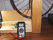
The prototype can now be spun to produce electricity. Wiring the charger up to recharge a battery requires some calculations as shown in the section below. The testing should be done at this stage to determine what voltages and amperages are able to be produced by the system. These are important parameters needed for the wiring of the protoype.
Wiring the charger[edit | edit source]
The circuit diagram for this battery recharger is shown in figure 5.
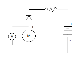
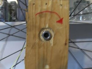
Firstly the proper current direction must be established. The red wire was chosen to be positive. Hook the positive lead of the voltmeter up to the red (positive) wire and the other lead to the black wire and spin the rim to determine which direction gives a positive voltage. Mark this on the support as shown in figure 6.
Some calculations need to be done to determine which resistor will be incorporated into the circuit.
This charger will use a charge rate of C/5 to be safe. This means it would take 5 hours to charge a fully discharged battery. Thankfully the battery is not completely depleted so it will not take this long to fully charge the battery. Since we are using a charging rate of C/5 this means that for 5 h the charge current will be 30mA (150mA/5).
Ohm's lawW is needed to determine the resistorW value required to keep the current at an acceptable rate for battery charging. Ohm's Law is expressed by the realtion;
[1]
Where V is the voltage in volts (V), I is the current in amperes (A) and R is the resistance in ohms Ω.
If the voltage has to be ~ 3.6V to charge the battery then we can rearrange the equation and solve for R. (watch the units as the current is in mA therefore divide the mA value by 1000 to convert to A)
Rearrange V=IR to R=V/I
Go here to find the colour of the proper resistor resistor colour guide
If there is not a resistor for this value you should normally round up to the next standard resistor to add a factor of safety into the design. However since we have already incorporated a factor of safety into the design by charging at a rate of C/5 a 100 ohm resistor will work fine as it gives a charging rate of (3.6V/100Ω = 0.036A = 36mA) which gives a charging rate of ~C/4.16. This is okay for the prototype although one should contact the battery manufacturer to get the optimum charge rate. Wire the circuit according to the wiring diagram in figure 5. It is useful to use alligator clips to connect the battery to the circuit. The diodeW is used to direct the current in only one direction so the battery does no try and power the motor. This is a crucial piece of the circuit. Be sure to connect the diode in the proper orientation.
Future Work[edit | edit source]
As discussed above it would be beneficial to have a water wheel design so a human does not constantly have to spin the rim. The rim should be converted into a water wheel and large buckets could be used as a water supply. Ideally a large bucket would be moutned with a spout the pours into another large bucket. When the top bucket pours over the water wheel the water is caught by the second barrel. The top barrel would have to be routinely filled but would require shorter time intervals of human work to charge the battery.
A pedal powered design would be a very effective human powered battery recharger. It should also be able to fit to any bike to increase its usefulness.
Relevant Links[edit | edit source]
Here are some relevant links for a water wheel design and pedal powered designs.
- Hydro-Electric-Barrel Generator[10]
- pedalpower.com][11]
- Alternative Energy News[12]
- You Tube Clip[13]
References[edit | edit source]
- ↑ Answers.com,"Storage Battery",http://www.answers.com/topic/battery-electricity,Accessed April 10, 2009
- ↑ Wikipedia, "Battery (electricity)", http://en.wikipedia.org/wiki/Battery_(electricity), Accessed April 10, 2009
- ↑ 3.0 3.1 Wikipedia, "Battery Charger", http://en.wikipedia.org/wiki/Battery_charger, Accessed April 10, 2009
- ↑ 4.0 4.1 4.2 4.3 4.4 4.5 4.6 Storey, N. (2006). Electronics A Systems Approach 3rd Edition. Hampshire: Pearson Education.
- ↑ Intelligent NiCd/NiMH Battery Charger - Construction Project http://www.angelfire.com/electronic/hayles/charge1.html Accessed: April 09, 2010
- ↑ 6.0 6.1 6.2 How Stuff Works, "How Batteries Work",http://electronics.howstuffworks.com/battery4.htm Accessed April 08, 2009
- ↑ 7.0 7.1 7.2 Energy Alternatives Ltd., "Battery Chargers" http://energyalternatives.ca/SystemDesign/chargers1.html Accessed: April 07, 2010
- ↑ 8.0 8.1 Leading Edge Hobbies, http://web.archive.org/web/20100612163240/http://www.leadingedgehobbies.com:80/oscommerce/catalog/default.php, Accessed: Aprile 10,2010
- ↑ Home Depot, http://web.archive.org/web/20201217175450/http://www.homedepot.ca/, Accessed: April 10, 2010
- ↑ Current.com "Hydro Electric Barrel Generator",http://current.com/12n164c, Accessed: April 12, 2010
- ↑ Pedal Power.com,http://www.pedalpowergenerator.com/, Accessed: April 09, 2010
- ↑ Alternative Energy News,"Pedal Powered Electricity Generator from Windstream",http://www.alternative-energy-news.info/pedal-powered-electricity-generator-windstream/, Accessed: April 09, 2010
- ↑ You Tube, "Mobile Pedal-Powered Generator",http://www.youtube.com/watch?v=wcY1ADGcrfs, Accessed: April 09,2010


