Head position sensor

Project[edit | edit source]
Make an enclosure & headphone band attachment for a cheap location & direction sensing circuit, which excels a 600 € commercial product. The accurate monitoring of the location and orientation of the head is vital for generation of virtual sound scenes for headphones.
Motivation
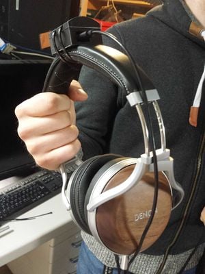
The reference point for this work are commercial location sensing products. Sometimes commercial solutions are less than optimal. For example this product costs 600 € and and still stable fixing to the headphones is rather difficult. If the sensor moves relative to the headphone, it is detected as the movement of the head and causes an undesired movement of the virtual sound environment.
-
A commercial alternative, 600 €.
Concept
A location sensing of the user head can be accomplished rather cheaply with a relatively low-cost 9 Degrees of Freedom location sensing circuit (gyroscope & gravity & accelerometer). For the best reaction speed the use of USB-cable for data transfer is preferred which also provides the power for the circuit.
The design we ended up after testing is rather simple: the circuit is fixed in an enclosure which is attached to the headphone band with 2 cable ties. The enclosure consists of the chassis, lid and an optional curved bottom part. The chassis part houses the circuit and provides a feed-through for the USB-cable. The lid snaps on the chassis and has tracks for the cable ties so the enclosure can not move laterally. If the headphone band has significant curvature which would cause possible "swinging" of the enclosure, the optional curved bottom part can be snapped to the bottom of the chassis part. The curvature of the bottom part can be adjusted with one parameter in the 3D model to match the curvature of the headphones, and has as the default a curvature matching the most of the headphones.
Bill of Materials[edit | edit source]
1) A location sensing circuit, for example SparkFun 9DoF Razor IMU M0
2) 3D printing filament
3) 4* M3x6mm screws (steel screws are probably also ok, paranoid people can also use plastic screws)
4) 2* cable ties (per one attachment), length at least 200 mm
Estimated Cost
| Quantity | Item | Unit price | Total price |
|---|---|---|---|
| 1 | SparkFun 9DoF Razor IMU M0 | 28.36 € ( $34.95 ) | 28.36 € |
| ~ 22 g | 3D printing filament | 0.07 €/g (at FabLab) | 1.54 |
| 4 | M3x6mm screw metal/plastic | 0.03/0.16 € | 0.12/0.64 € |
| 2 | 200mm cable ties | 0.04 € | 0.08 € |
| In total | 30,62 € |
Savings per piece: 569 € = 95 %.
Directions[edit | edit source]
1) Download the model from here.
2.1) If using SparkFun 9DoF Razor IMU M0, simply print the model: one of each part but four snaps.
2.1) If using another circuit board, modify the dimensions of the circuit and the location of the USB-connector in the Openscad model, accordingly.
3) Initialise the threads of the chassis with a metallic M3 screw. (The 3D printed threads are not perfect.)
4) Fix the circuit to the chassis with four M3 screws.
5) Snap in the lid and the curved bottom part if desired.
6) Fix the enclosure to the headphone band with 2 cable ties.
7) Enjoy the soundscape.
Designer
Antti Karjalainen, Department of Applied Physics, Aalto University
In collaboration with a friend of mine at the Department of Signal Processing and Acoustics, Aalto University
Images of finished parts[edit | edit source]
-
1. Chassis
-
2. Lid
-
3. Optional curved bottom
-
3. The snaps holes of the curved bottom and the snap pins at the behing
Assembly pictures[edit | edit source]
-
Circuit in the chassis
-
Hole for the USB-cable
-
Fully assembled project
"After work"[edit | edit source]
Creator comments on the design
1) First, a more sophisticated snap-on mechanism was prototyped for the attachment to the headphone band. Attachment via cable ties turned out to be superior due to A) it can fit to headphone bands of different dimensions: a snap-on method would need a headphone-specific adapter, B) with cable tie fitting the printed model is more robust, C) cable tie strength
2) Fixing of the circuit board with (M3) screws is more practical than with snaps. The device has to stand a number of attachments and removals of the USB-connector and a snap-on fixing wouldn't most probably provide that.
Improvement ideas
1) Due to the precence of the cable ties, the cover will stay in place during the use if the lateral movement is prevented. So "tight fit" based snap-on is not necessarily required and the simplification of the model is possible.
2) Can the need for the screws be eliminated?