
Filing is probably the most important and the most frequent operation in metalwork. It should be the first process learned by the metalworker, and it happens to be a rather difficult process to master. While the subject of files was discussed briefly in Section One, in connection with woodworking, it might be well, to enlarge a little on this subject as it is applied to metalwork. The file consists of a blade with a tang for attachment to a wood handle. The handles can be purchased for a few cents or made in the home workshop. In any case, each file should be fitted with a handle because it is very easy to injure the hand on the sharp file tang. Teeth of a suitable kind are cut on the blade which is then hardened and tempered.
The wide variety of operations in which filing is required makes it necessary that there should be a large selection of files available. There is a file for almost every job, and some types will do the job better and faster than others. As files are relatively inexpensive, anyone who plans considerable work with metals can have a rather complete set of them.
Files are classified and named according to three factors, length, sectional form, and the type or cut of the teeth. The length will vary considerably – all the way from 4 inches to about 20 inches. The length of the file does not include the tang (see Fig. 1). The tang of the file is tempered so as to be soft and tough; if it were as hard and brittle as the blade it would be easily broken where the handle meets the blade.
For general work, a file from 10 inches to 16 inches is adequate. For small jobs, use files from 4 inches to 6 inches in length.
Cut of the Teeth. The number of teeth per inch varies slightly according to the brand of file, but the following list represents a fair average:
- Rough, 20 teeth per inch
- Middle, 25 teeth per inch
- Bastard, 30 teeth per inch
- Second Cut, 40 teeth per inch
- Smooth, 50 to 60 teeth per inch
- Dead. Smooth, 100 or more teeth per inch
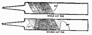
The teeth may be either single cut or double cut, as indicated in Fig. 2. On single-cut files the teeth are cut parallel to each other across the file and at an angle of from 65 to 85 degrees to the center line. Single-cut files are used chiefly on very hard. metal. In a double-cut file there are two sets of teeth, the first or over-cut teeth being cut at 40 to 45 degrees to the center line and the second cut or up cut at 70 to 80 degrees to the center line. The shape of the teeth has been carefully calculated. It may be seen on examination that the front part of the tooth slopes backward, giving it a negative rake. The width at the base of each tooth is important, for teeth which are too narrow for their height are easily chipped and broken off. The angle of the cut to the axis of the file is designed so that a slicing cut is obtained, causing the metal to curl off much more readily than if each tooth met the metal along its whole length at the same time.
Files are designed especially for use on one particular kind of material. For wrought iron the cuts are best at 80 degrees and 60 degrees, while for brass filing the up cut is nearly 90 degrees.
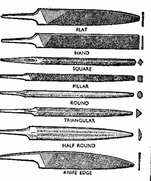
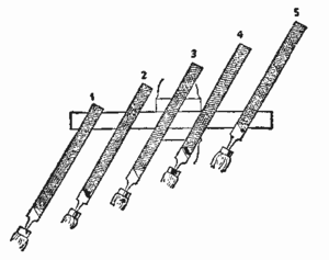
Fig. 3 shows the more common file shapes, along with their names.
Standard Types. Flat files are always double cut on the faces and single cut on the edges, and. they taper both in width and thickness toward, the end. The hand file is parallel in its width, and in thickness it tapers slightly from a point about one-third of its length from the base. One edge is left uncut, a help when filing angles or where on1y one surface must be filed without touching the other.
Pillar files are narrow and of rectangular section; they may be parallel or tapered and are usually double cut, having one or two edges uncut (or safe). The square file is double cut on each face and is normally tapered for the last third of its length. Round files are generally single cut and are usually tapered, in which case they are called rat-tailed. When parallel they are described as parallel round. Half-round files are generally double cut on the flat face and single cut on the curved surface. The section is not actually semicircular, and the files taper for the last third of their length, both in width and in thickness, as shown in Fig. 3.
Triangular files are either single or double cut and. taper to a point from about two-thirds of their length from the tip. This is the type of file used for sharpening a hand-saw. Knife files are used for cleaning out acute-angled corners. Both faces are double cut and the edge single cut.
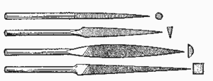
For very fine and delicate work a needle file is used. These range in size from 4 inches to 8 inches. They are very fragile and easily broken (see Fig. 4).
Care of Files. Like any other tool, a file should be handled carefully, since its period of usefulness can be considerably prolonged by correct use. The wood handle should fit well; otherwise, there is a tendency to produce a curved. surface because the handle and the file are not held firmly in line with each other.
If files are thrown in a box with other files or metal tools, the teeth are likely to be damaged, and the file is then useless. It is a good policy to hang files in a rack such as that used for wood chisels and wood bits. Not only will this prevent the file from being damaged but it also makes it easy to put your hand on the right file without having to waste time hunting in the tool box. Another good way to store files is in a large drawer with a wood partition between each file. A file should be kept free of rust, as this corrosion will dull the sharp edges of the teeth and the file will not cut properly. Files are rather brittle and should never be used to pry objects apart or for any other job except filing.
The life of a file can be extended considerably by using it on soft metals, such as copper and aluminum, when it is new and using it on the harder metals as the teeth become dulled. If a new file is used on hard metals, the teeth will soon become so dulled that it will be of no use in the shop.

With use, the teeth of a file will become filled with small bits of metal, particularly when working with soft, nonferrous metals. A wire brush or file card must be used to remove these bits of metal. If this is not done the file will scratch the surface of the metal being worked upon and at the same time work less effectively.
Brush the file card across the file so that the bristles run along the lines of teeth and push the stuck-in bits of metal out sideways. Never run the file card along the length of the file, it dulls the teeth and doesn't clean the file effectively.
If you don't have a file card you can use a scrap of brass or similar soft metal. Rub the piece of brass backwards and forwards along a row of teeth until a matching set of teeth are cut into the piece of brass. You can then rub this brass comb across the file and the brass teeth will lift out the stuck-in pieces of metal.

Using the File. The manner in which the file is held and the right working height are important. The height of the vise in which the metal is held should be such that with a bent arm the elbow is on the same level as the top of the vise. It may be necessary to build a small wood platform on which to stand, so that the proper working position can be obtained. The feet should be well apart with the left foot about 24 inches in front of the right. The file may be held either with the handle in the right hand and the top of the file in the left hand or vice versa. It will only be necessary to discuss the former case, since the position of the hands will merely be reversed for the left-handed worker. The position of the left hand on the tip of the file should be varied according to the type of work or file in use, but the grip of the right hand on the handle is always the same as is shown in Figs. 6, 7, and 8. The file handle rests in the palm of the hand, the thumb is along the top of the handle, and the index Finger points along the side. This grip enables the file to be kept perfectly level while weight is applied first to the left hand at the beginning of the stroke, then to both hands equally in the middle of the stroke, and finally to the right hand at the end of the stroke.

The tip of the file should be gripped with the left hand as shown in Fig. 6 where the tip of the file is under the palm of the hand and all the fingers are underneath. This is a powerful grip and one which enables the maximum. weight to be applied. It is consequently used with a medium or long file on work which requires a large quantity of material to be removed.
Fig. 7 shows a better position for doing more accurate work, when using the smaller files, and. when filing curved surfaces. It will be seen that the tip of the file is held by the thumb and index finger.
In the third method (Fig. 8) the thumb and fingers are stretched as far as possible and are evenly against the file. This ensures that the weight is more evenly distributed over the whole length of the file so that there is a greater tendency for it to remain horizontal.
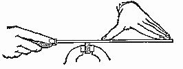
Do not let the file rock or seesaw, as this will produce a rounded surface. This can be avoided if care is taken to keep the body still and to make the arms pivot about the shoulders.
When working on a narrow piece of metal, it is often easier to keep a flat surface if the file is held diagonally to the work, filing forward and to the left in one continuous movement and then, after a few strokes, going forward and to the right. This is shown in Fig. 9. Hold the file, firmly.
Apply downward pressure on the forward stroke only, drawing the file lightly backward without actually lifting it from the face of the work. This should be done because the teeth are designed to cut on the forward stroke only, and any pressure applied on the backward stroke serves to dull the teeth more quickly without serving any useful purpose.
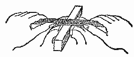
After a piece of work has been filed to the proper shape, it is finished by draw-filing. Hold the file as illustrated in Fig. 10, placing the fingers on the edge away from the body and the two thumbs on the edge toward the body. Draw and push the file along the surface with an even pressure. A smooth file is used, and this makes comparatively fine cuts or scratches in the work, parallel to the longest edges. This gives a much better appearance than scratches running across the surface.
A sharp wire edge will be produced in draw-filing on each edge of the surface being filed; this is easily removed by holding the file at an angle and running it lightly down each edge. In doing this, the tip of the file (safe or smooth edge down) should be supported on the jaws of the vise. The final finish can be achieved by polishing with fine emery cloth and oil. A surface treated in this manner will withstand rust better unless, of course, the metal is to be painted.
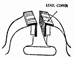
When working with metals with a high polish, great care must be taken not to let the jaws of the vise damage the metal surface. The jaws of a vise are usually cut much the same as a file in order to secure a firm grip on the work. It can be easily seen that these jaws would. mar any highly polished surface. To avoid this, the jaws of the vise can be fitted with clamps made out of soft metal, such as copper or brass or, if the metal has a very high polish, wood or leather (see Fig. 11).
It is sometimes possible to renew the life of a file that has been carelessly treated, by boiling it in a strong solution of soda and water for a few minutes; this re- moves the grease and rust, and after scrubbing with a file card or wire brush the file should be dipped in kerosene.
To be certain of filing true, it is necessary to test the work frequently. An ordinary steel rule or the blade of a try square held on the work and against the light will give a fairly accurate test of straightness; any hollows are clearly shown by the light shining under the straightedge.
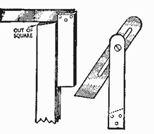
Right angles are tested. with the try square, and angles which are not 90 degrees may be tested with a bevel square set to the required angle (Fig. 12).
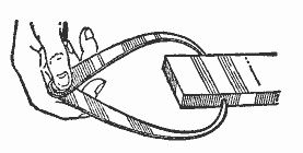
Outside calipers (Fig.13) can be used to test the edges of a narrow piece of metal to find if they are parallel. Any difference in width is easily noticed by the uneven grip of the caliper points.