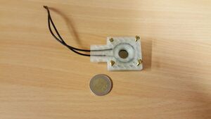
Electroplating holder

Electroplating holder that allows deposition on fixed area on sample and has contacts that are isolated from electrolyte.
Introduction[edit | edit source]
Electroplating on limited area on a sample requires means to prevent electrolyte contact or insulating material in the areas that are not be coated. This is usually achieved by either patterning the conductive layer on the sample or by masking parts of the sample with insulating material.
Here the aim is to define center area of the sample to be plated by isolating the rest of the sample and contacts with O-rings. This way it is possible to have continuous seed-layer on the sample while plating only in the center of the sample. Samples we typically use are pieces of silicon wafers with seed layer, which are easy to cleave to 2x2 cm squares and have known thickness of 525 µm.
This project was performed as a final project of the L3999 course Fall 2017.
Design[edit | edit source]
The electroplating holder consists of two 3D printed parts, 2 O-rings, contacts and wiring. The inner O-ring defines the plated area on the sample and isolates the contact area from electrolyte from inside when the top and bottom parts are squeezed together. The outer O-ring isolates the contact area and sample from electrolyte from the outside. The two parts are pressed together with bolts and nuts.
The scad file and stl files for printing are available at https://3dprint.nih.gov/discover/3dpx-008215. In the Scad file sufficient comments are given to make it easy to change holder dimensions. However, it is not guaranteed that all possible dimensions work and hence it should always be checked that the changes to dimensions do not break the structure.
- Design
-
Bottom piece back.
-
Bottom piece front.
-
Top front.
-
Top back.
- Printed and assembled
Printing were done with Lulzbot Mini using transparent PLA.
Printing instructions[edit | edit source]
The bottom and top part should be printed separately or side by side with O-ring sides facing upwards.
Bill of materials and Costs[edit | edit source]
- 2 3D-printed parts consume 17 g of PLA
- 4 bolts and nuts
- 4 springs (e.g. cut off from ballpoint pen spring)
- ~ 15 cm of wire
The 3D-printed parts consume ~17 g of material, which costs approximately 56 cents (750 g PLA costs ~33 € in Finland) and takes about 2 hr to print with high detail settings that were used. In addition to this 2 O-rings are required. The ones used in the design cost 2.65 € in total. In addition bolts and nuts to squeeze the top and bottom together are required that cost ~1€. Springs can be used to create contact with the sample. These can be made from ballpoint pen springs.
Total cost 5 €.
Savings compared to conventional way of masking areas by taping: Time and nerves (hopefully).
Ideas for further modifications[edit | edit source]
- Add springs beneath the sample stage to press the sample against O-ring and contacts.
- allow different sample thicknesses with same holder
- adjust the force applied on the sample when the two pieces are fastened together


