Athena Dual Extrusion Single Hotend
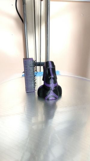
Dual extrusion opens up many possibilities for 3D printing. The most obvious use for dual extrusion is to have 2 color models printed. However there are even more useful ways to take advantage of dual extrusion such as being able to print a dissolvable support material which will allow you to print much more complicated geometries than would otherwise be possible as you no longer have to worry about overhangs and bridging.
The traditional method for dual extrusion has been to use two hotends and two extruders. This method however requires extra hardware and reduces the size of your build space. Also this method requires careful calibration of nozzle heights to insure that the nozzle not in use is not hitting the printed part. Often times the results with these dual extrusion setups have ooze from the nozzle not in use ending up on the printed part and other artifacts.
The dual extrusion solution that I have chosen is one which uses a single hotend and only requires the addition of another extruder and a printed part to merge the outputs of the two filament extruders. This solution has the advantage of requiring no additional calibration, not needing added hardware for the second hotend and inputs and outputs to drive that hotend, and maintaining full build volume.
Cura 2 Support coming![edit | edit source]
I am currently working with making Cura 2 compatible. This will hopefully allow for dual extrusion to be more easily used for support material especially with dissolvable supports like PVA.
Example Prints[edit | edit source]
-
Dual extrusion print with the prime tower
-
Dual extrusion cat model
-
Dual extrusion cat model with prime tower still on bed
Design[edit | edit source]
For this modification I have used the bowden tube merger by AxMod found here. It uses the same PC4-M6 bowden tube connectors used elsewhere on the printer.
The second extruder used is the same as the one already used on the Athena printers and the file for it can be found here and the required SCAD libraries here. The drive gear dimensions for the extruder should be changed to match those of the drive gear which you are using.
Construction and BOM[edit | edit source]
Bill of Materials[edit | edit source]
| Item | Quantity | Price |
|---|---|---|
| Extruder Body | 1 | cost of filament |
| Bowden Tube Merger | 1 | cost of filament |
| PC4-M6 fittings | 4 | $6.99 (10) |
| Bowden Tubing | 1.5m | $6.49 |
| A4988 Stepper Driver | 1 | $9.69 (5) |
| 100µF 35V cpacitor | 1 | $0.35 |
| Nema 17 Stepper Motor | 1 | $11.99 |
| 608ZZ Bearing | 1 | $7.32 (10) |
| MR105ZZ Bearing | 1 | $10.49 |
| 1/4" Fuel Line | 25mm | $7.95 (5 ft) |
| MK7 Drive Gear | 1 | $6.99 (2) |
| M3 washer | 2 | |
| M3 Nut | 2 | |
| M3 x 6 Cap Head Screw | 1 | |
| M3 x 25 Cap Head Screw | 1 | |
| M3 x 30 Cap Head Screw | 2 | |
| M3 x 45 Cap Head Screw | 2 | |
| #6 x 1/2" sheet metal screw | 2 | |
| Misc Wiring | ||
| Total Cost | $65.26 | |
Construction and Setup[edit | edit source]
Tools needed:
- Soldering Iron
- Desoldering Braid
- 2.5mm Hex Wrench
- 2mm Hex Wrench
- File
- Wire Stripper
- Knife
Steps:
- Print extruder body and bowden tube merger. Note that you may need to change the dimensions of the drive gear in the OpenSCAD for the extruder body. Do this by measuring the diameter and diameter of the hobbed section with a calipers and inputting these values into the extruder_drive_renderer file.
- Wiring Wiring diagrams and stepper driver info. More stepper driver info for non-pololu driver boards.
- Remove the Bridge Board from the melzi and beaglebone and disconnect it's power.
- Desolder the DC-DC converter from the top of the bridge board to gain access to the pins below it.
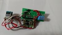
- At this point you will want to solder three wires to the unused pins on the bridge board. These will be the pins to control the stepper driver. I have chosen to use pins A1, A2, and A3 as pictured. However only pins D10, D11, and A4 are already used on this header so other options would also work.
- You will then need to resolder the dc-dc converter. You can solder it in place as originally done with your control wires running underneath however I have chosen to have it connected with a short bit of wiring so that I still have access to the pin header.
- Finally you need to solder two sets of power wires to the dc-dc converter for your stepper driver. You will need both the 24v and the 5v lines for the stepper driver (Fig 1).
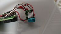
- You are now ready to wire up and connect the stepper driver. Connect the 24v supply to Vmot and GND with at lest a 47µF bypass capacitor soldered very close to or on the board (Fig 2).
- Then solder the 5v supply to Vdd and GND.
- Connect the Sleep and Reset pins together.
- Now wire your three control wires to Enable, Step, and Dir. The order in which you wire them is not important just take note of it as you will need to enter it in the firmware later.
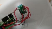
- Finally connect Vdd to MS1, MS2, and MS3 to enable 1/16 microstepping (Fig 3).
- Now plug the bridge board back into the melzi and beaglebone and reconnect it's power to the dc-dc converter.
- Now simply plug in with pin headers or solder your stepper motor to the 1A, 1B, 2A, 2B pins making sure to wire it correctly (consult the pololu page).
- You will also need to power on the system and trim the current regulation voltage. Note that not all drivers use the same value sense resistor. The value of the sense resistor will change what Vref you will want to set for a given current limit. The formula for current limit on the A4988 driver is Vref = 8 * Imax * Rs where Vref is your reference voltage in volts, Imax is your current limit in amps, and Rs is your sense resistor value in ohms.
- Now go ahead and mount the stepper motor to the extruder drive per the instructions in the build guide. Athena Extruder Drive and Spool Holder Assembly
- Cut a length of teflon tubing about equal to the one already connected to your first extruder and push it into the coupling on the new extruder.
- Put a coupling onto all 3 ports of the extruder merger.
- Cut a short piece of teflon tubing just a long enough that it sticks out of the hotend just a bit and there is only a small gap when you push the extruder merger coupling onto it.
- Now connect both extruders tubes to the extruder merger.
- Franklin
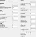
- In Franklin set the number of extruders to 2 (Fig 4).
- Then make sure that you leave the extruder offset at 0 for both extruders (Fig 5).
- Finally you will need to setup the outputs to control the second extruder motor. Enter the name of the pin which you have connected to the corresponding pin on the stepper driver. Depending on how you have wired the stepper motor you may have to check or not check the box for inverting next to the Dir output. Enable should be set to inverting (Fig 6).
- Slicer Setup and G-Code
- In Cura 15.04 you will want to open the machine settings and set extruder count to 2. Also make sure you set extruder 2 offsets to 0 (Fig 7).
- Next you will want to setup the expert settings. In the expert settings window set your wipe and prime tower volume between 35 and 45. Also make sure to enable wipe and prime tower under the dual extrusion settings in Cura (Fig 8).
- In cura's Start/End-GCode tab you will want to enter the following.
For start2.gcode enter
;Basic settings: Layer height: {layer_height} Walls: {wall_thickness} Fill: {fill_density}
;Print time: {print_time}
;Filament used: {filament_amount}m {filament_weight}g
;Filament cost: {filament_cost}
;M190 S{print_bed_temperature} ;Uncomment to add your own bed temperature line
;M104 S{print_temperature} ;Uncomment to add your own temperature line
M109 T0 S{print_temperature} ;Uncomment to add your own temperature line
G21 ;metric values
G28 ;move to endstops
T0 ;Switch to the first extruder
G1 E140 F600
G92 E0
G1 F1500
G1 Z0.15 Y122 X0 E2
G1 X21.18 Y120.14 E4
G1 X41.72 Y114.64 E6
G1 X61 Y105.65 E8
G1 X78.42 Y93.45 E10
G1 X93.45 Y78.42 E12
G1 X105.65 Y61 E14
G92 E0
For preSwitchExtruder.gcode enter
G91
G1 E-5 F10000
G1 E2 F10000
G1 E-135 F10000
G90
G92 E0
For postSwitchExtruder.gcode enter
G91
G1 E138 F600
G90
G92 E0
Finally for end2.gcode enter
M104 T0 S0
M104 T1 S0 ;extruder heater off
M140 S0 ;heated bed heater off (if you have it)
G91 ;relative positioning
G1 Z+20 Y+20 F8000 ;move up and back
G1 E-5 F10000
G1 E2 F10000
G1 E-135 F10000
G28 ;move to endstops
M84 ;steppers off
G90 ;absolute positioning
;{profile_string}
You may need to change the retract amount slightly. Here I have used -138mm of total retract. I have found it best to set it to an amount wich has the filament stopping just inside the extruder merger but obviously beyond the y junction point.
Printing[edit | edit source]
Before starting a print you will need to load the filament I have found that it is best to load the filament all the way into the hotend while it is cold and then retract it the same distance you have set in your G-Code (138mm in my case). Do this for both extrruders before starting a print. Once you have done this setup you can run several prints in a row without having to redo this as long as you do not change filaments. You should now be ready to start a dual extrusion print.
Currently I have only tried printing with two colors of the same material. I would like to try using two different materials in the future either for disolvable supports or for interesting dual material property prints. With the current setup you would need to print both materials at the same temperature but with some adaptations to the G-Code you should be able to print at two different temperatures and even use the time while it prints the prime tower to get the hotend up to or back down to the correct temperature.
Material[edit | edit source]
I have tested this with the following materials. Please feel free to add materials which you have had success with along with any notes about it.
Common Problems[edit | edit source]
- There does seem to be some sort of bug in the Franklin firmware that will cause the printer to pause when running the tool change script. This problem only happens with certain G-code setups though and I have been unable to determine what causes it. My current G-code does not have this issue.
- Make sure your hotend temps are high enough to prevent jamming of the material. Standard filament temperatures seem to work fine but just don't go too cold.


