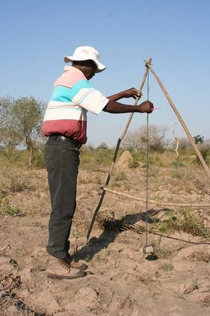
The A Frame is an A shaped structure made from wooden poles or thin metal poles that can be easily constructed and used to peg flat or graded contours or water drains. These contours are mostly used as soil and water conservation structures. Where rainfall runoff is less, i.e. less than 600 mm of poorly distributed rains it is advisable to make flat contours whereas where there are chances of water-logging it is advisable to slightly grade the contour to allow water drainage.
The justification[edit | edit source]
There are a number of reasons why one could choose to use the A Frame for pegging compared to pegging with a machine i.e. a kern level, an automatic level or a theodolite.
The main advantage of the a frame is that it can be constructed very easily using local materials and literacy is not essential for making and using it. When farmers are faced with a developing gully or erosion in their field they often don't just look while the soil is being washed but rather improvise to save the situation. In that bid they often exacerbate the situation by digging down the slope or make ditches that are very graded. The A Frame at least assists the farmer to safely peg and construct contours that save the soil. In some countries those mandated to peg may not have adequate resources like transport and equipment to service farmers. It is extremely important that farmers know how to peg and dig contours because contours are very important as they form the first line of defence against erosion and they are the backbone for all other in field conservation works.
How to make the A Frame[edit | edit source]
Materials required
- 2 x 3 metre poles
- 1 rail (pole) 1.5 metre long
- Stone weight or half brick
- 2.6 metre long string
- 3 x 5 cm nails or tying wire
Construction procedure[edit | edit source]
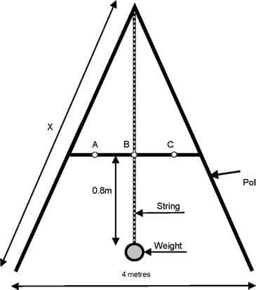
- Nail together the top of the 3 metre poles so that there is an inverted V form. These poles should be thin, at most 3 cm in diameter.
- Open the base of the V until its 4 metres.
- From the pivot of the V measure 2.2 metres going down and mark on 3 m sides or 0.8m from the bottom.
- Nail the 1.5m rail across the 2 legs on these marks.
- From the apex suspend a string at whose end there should be a stone or half brick knotted on. This is called a bob.
- You may add an extra strength by putting 2 or 3 rounds of tying wire over the nail positions.
- The A Frame is now complete.
Calibrating the a frame[edit | edit source]
- Stand the A Frame and mark the positions of both legs on uneven ground.
- Wait for the string and weight to pendulum and finally rest.
- Mark the position onto which the string is on the rail = A.
- Exchange the leg positions.
- Allow the string and weight to rest after swinging.
- Mark position on rail B.
- Measure the distance between A and B.
- Divide the total distance by 2 to find the A Frame centre.
- This centre is now where the string position should be when the correct position of a peg is being sought.
- Such a calibrated centre is for making dead or flat contours
How to peg with the A Frame[edit | edit source]
- Make an overview of the whole portion to be pegged.
- Mark out crests and waterways.
- Start from the crest proceeding to the waterway and not vice versa.
- Place the A Frame striding the peg from which you are starting from, with the bob over the peg and the string at the calibrated frame centre.
- Start from the crest proceeding to the waterway.
- Moving towards the waterway, with the waterway leg as a pivot, swing the crest leg until it is in the water way direction until the string pendulums to the calibrated frame centre.
- Put a peg under the bob or just any mark.
- Now with the water way-ward level peg fixed switch the now crest-ward leg until the string is at the calibrated frame centre.
- Put a peg under the bob or just a mark.
- Continue 7, 8 and 9 until you get to the waterway.
Marking out and digging the contours[edit | edit source]
- After reaching the waterway connect the pegged points together until there is a continuous line.
- Smoothen out very bend points but taking into account not to ignore dips and crests.
- Dig out the contour to your desired depth and width.
References and further reading[edit | edit source]
- Dead Level Contours (Practical Action Technical Brief)
- Field Surveying for Land and Water Management: Agrodok No 6 by van Dijk N, Spaans H & Mechielsen F, Agromisa
- Simple Methods of Preventing Soil Erosion and Conserving Water: On a Technical Note by Nigel Walsh Baobab issue No 1, ALIN, 1988
- Contour barriers, Tearfund http://web.archive.org/web/20120810201833/http://tilz.tearfund.org:80/Publications/Footsteps+61-70/Footsteps+70/Contour+barriers.htm
- How to Construct the A-frame Agroforestry Information Network
http://web.archive.org/web/20080427040721/http://www.pcarrd.dost.gov.ph:80/CIN/AFIN/A-frame.htm


