
Safety Training Requirements[edit | edit source]
- Dr. Pearce Safety Lab Tour
- Worker Health & Safety Awareness
- WHMIS 2015 - Workplace Hazardous Materials Information System
- Laboratory Safety & Hazardous Waste Management
Rodeostat[edit | edit source]
- TEB7
- IO Rodeo
- https://iorodeo.com/products/rodeostat
Operation & Procedure[edit | edit source]
The instrument works in two ways:
1- Web-based application
The web-based application is straightforward to use.
2- Python library
For the Python library on Windows, follow these steps:
- Insert the USB cable into your computer.
- Run the code provided in the Github repository
- Before testing the battery, use a dummy cell to calibrate the instrument. Use the calibration code available on Github. The figure displayed after running the code should resemble the example shown in Figure 1.

Fig 1. calibration: cyclic voltammetry with a 50K dummy cell - It is taped on top of the device (Figure 2).
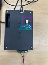
Fig 2. Dummy cell - After calibration, use the battery holder which is a 3D-printed clip to connect the battery to the device. The battery should be placed between two washers, as shown in Figure 3.
- Connect the alligator clip attached to the Rodeostat to the battery. The working electrode alligator clip should be connected to the electrode you are testing (e.g., a 3D-printed anode). The other side of the battery serves as both the counter electrode and working electrode; attach the alligator clip to the wire coming from this side (Figure 3).


Important Note:
The current range of the device is limited to '1 µA', '10 µA', '100 µA', and '1000 µA'. The internal resistance of the device is basically determined by the digitally controlled analog switches used to connect or disconnect the electrodes, and the on-state resistance (Ron) of these switches is quite low. If you don't use an appropriate resistance, the device will become saturated and won’t function properly.
To prevent saturation and keep the current draw within a reasonable range, you need to place a correctly sized resistor in series with the battery cell (Figure 3). To calculate the necessary resistance, use Ohm's law:
V=IR, where V is the voltage between the CTR/REF and WRK electrodes, I is the desired current (limited to the device current range), and R is the resistance that should be used in series with the battery cell.
For example, if the voltage between the CTR/REF and WRK electrodes is 3V and you want to limit the current draw to less than 90 µA, you would need a 33kΩ resistor in series with the battery.

- Once everything is set up, the Rodeostat is ready to run (Figure 4).
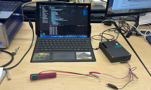
Fig 4. Assembled Rodeostat

References[edit | edit source]