
- Full name: Robert Daniel Butler
- Current College Junior
- Double majors in Theatre and Business Administration
- Current Student Body Vice President
- www.linkedin.com/robby-butler
Why I'm here[edit | edit source]
This project reflects my first steps into the open-source movement, and will include my first strong example of participation in the movement. This will involve both giving and taking of the benefits of open-source information, with a conscious choice to not only take what I can but give what I can as well.
Because of the key element of sharing which has created the open-source movement, I'm drawn to it. It pushes back against a closed-door, close-minded business model of him-vs.-her, me-or-you, which is so prevalent in the world today. It takes some courage to try a new model, but we can be grateful that this movement was begun with courage and we're following in the footsteps of some great believers in the power of open-source.
By creating the JellyBox 3D Printer, my class got to experience one of the great advantages of the open-source movement. We were able to create something of a unique complexity and opportunity all through internet help guides (and some guidance from the original designer). However, we could have relied entirely upon our own desire to guide us through this process, since the build was truly open. Through the open-source movement, we have been empowered to take on projects like these, and have a high chance of success with them because we knew the resources to build them were so... open!
In the future, I will continue to learn about how to contribute to the movement. What's important to service in any movement is a broad enough understanding of its nuances that you are able to communicate effectively within the movement, and I will apply myself to learning not only how to contribute, but where. Uploading the designs that I learn to create will be an easy first step into returning what I have been given by joining this facet of the open-source movement.

- where you might go with it in the future
- [[Category:242-2017 People]]
- eventually galleries of your work from the class
Variable Testing Using PASCO Coupons[edit | edit source]
We printed 6 standardized test coupons to test for different print variables of our choice. 3 of the test coupons were printed vertically; 3 were printed horizontally. This accounted for our first variable adjustment, because as we stress-test the coupons, we will see that pulling apart the individual layers has a different effect than pulling apart strands of fused filament.
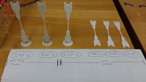
I decided to test print heat as well. This was an area I was not as familiar with in the testing of my printer so far, and so I am curious to see what the results will be. For both the 3 vertical and 3 horizontal coupons, I printed a coupon at:
- 200 degrees Celsius
- 210 degrees
- 220 degrees
My consistent print details are:
- 0.3 mm layer height (resolution)
- 50 mm/s print speed
- 100% flow speed (.4mm extruder nozzle)
- White PLA from Makerbot (with the exception of my final two vertical prints - I ran out of that color and switched to warm gray, from the same company).
Makerbot's PLA is reliable and affordable, so I anticipated no real problems from the material itself. As I viewed my prints, I could occasionally see the difference between 200 and 220 degrees Celcius. One caused a lot more strands to occur during printerhead travel than seems normal, which took a short time to develop. Also, since I didn't adjust print speed, my printer printed the vertical prints at a very high speed. Because of the thickness of the layer height and fineness of the coupon's center, this made for a sloppy vertical print. I haven't seen anything so jagged come out of my printer yet. I imagine this will affect quality in a secondary manner. I included a skirt in every print I did to ensure that extra filament was handled before starting on the regular print. The prints included 100% infill to test for maximum strength. The fan ran at either 50% or 100% depending on the area being printed, but this variable remained consistent throughout and shouldn't affect print quality.
To handle the first variable, I hypothesize that Prints made horizontally will survive higher levels of strain than vertically created prints. My second hypothesis, accounting for the second variable, is that Prints made at a higher temperature will survive higher levels of strain than lower-level prints.
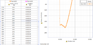
After testing, I found both of these hypotheses to be correct. The higher-heat prints survived more newtons of force, and elongated less, than the lower-heat counterparts. The horizontal prints were also stronger than their vertically-printed counterparts. On the left is an example of my best stress-test graph, with a horizontal coupon printed at 220 degrees Celcius. This print withstood 245 Newtons of tension trying to pull it apart, while only elongating 0.13 mm.
So, in summary, I will print future prints at a higher temperature in order to bond the plastic material better. Our printers offer a heat testing feature which I have yet to explore, and this step seems like a logical way to pursue greater understanding of how print temperatures affect quality.
Minimash Project[edit | edit source]
For our next class project, we had to take a celtic design and fuse it to something else we created. I was given a bookend as my object, and included a simple tri-point celtic knot as my artistic addition. It can be downloaded here!
https://www.youmagine.com/designs/celtic-bookend-43-41
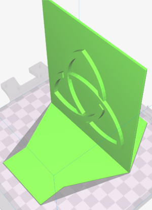
This was a moderate success. I learned a lot about layer thickness and the relative reinforcement that additional layers creates. I printed this design far too thin to really feel substantial, and although it will hold up most books, it does not have the durability that one would want from a bookend. Also, since I did not remove internal geometry from the design itself, the mesh did not happen as smoothly as I would have liked, and the parts actually have a micrometer of separation due to the improper mesh technique I used. This was all part of the learning curve of meshing two designs, but this would be an easy fix with the right tools.
OSH Science Project[edit | edit source]
For this project, Grant Larsen has requested a few trial pieces of a 3D printed part designed last summer for the physics lab. The current part (a portion of a whole circle) is a slice of an arc, about 165 mm by 45 mm by 14 mm tall, with magnet bays located on the inside. There is a lid of the same width and length proportions, which displays degree measurements.
The error in the current part is that the part was originally printed with a radius of 800 mm. The part was supposed to print with a radius of 1 m, or 1000 mm. Oddly, the original part had the same length dimensions as intended, but due to the error in the radius measurement, the arc was much sharper (as the circle was smaller).
I am tasked with two different trials to get the correct part for the circle:
1: Scale and print the project to see if it comes out proportionally correct, which will tell Grant Larsen if the original error (which messed up the radius of the circle) was a print error or a user error.
2. Take the original CAD design, cut off the edges to make it fit my print bed, relocate the magnet bays, and see if I can create the correct part with the correct inner radius.

I began with an initial CAD draft of the requested part. I took the draft designed part to my printer, and also printed the first layer of the original CAD to compare. This did not turn out the way I wanted it to. The inner radius of the circle (the crucial measurement of this part) was just as incorrect as their first part. Without any clue about what caused this issue, I decided to simply redisgn, and print the first few layers to examine the arc.
This second print was perfect. After Mr. Larsen and I celebrated this success, we determined that in my current printer bed, the part would be too short to be useful to the Physics Department. After some creative thinking, we decided to print the part at double length, but split in half so that it could be glued together and serve the Department more effectively. This print was near-perfect. Although I'm still waiting on an official confirmation from the Department, I am confident they will be pleased!
Open Source Appropriate Technology Project[edit | edit source]
For my OSAT project, I decided to 3D print grips for bike handlebars. Bikes are extremely efficient forms of travel in developing countries, and bike grips make the bikes comfortable to ride over long distances. Working in FreeCAD, I chose a simple design to start with. I used my own bike's handlebar as a framework for how to design the sizes of the grip.
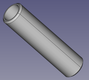
After having learned a lot about FreeCAD's functionality, I knew I had the tools to design something great out of my concepts. After recognizing that the basic tube design wouldn't provide any challenge, I changed the design to include finger-spacers between all four fingers, some chamfered edges to smooth the surfaces, and some mechanical additions to hold the grips firmly in place. This design was highly enjoyable, and so I printed it shortly after completion.
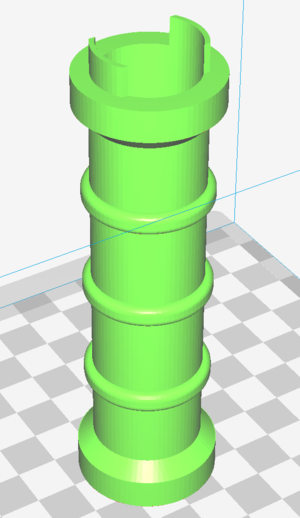
I was extremely pleased with this print (see final photo in this section). Even the overhangs on my print were extremely tight and well-printed, the sizing was right, the shell layers and infill percentages preserved ink while making the part feel DANG strong, and it slid right onto my bike handlebar! The only issue was one false estimate. The catchpiece visible at the top of the CAD drawing which held the grip on and prevented it from rotating was slightly too small, and it allowed the grip to freely rotate several degrees each way. Other than this poor estimate of size, the first try was perfect. Now onto the other grip.
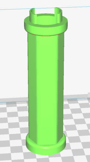
After the experience of the first grip, I knew (as much as I loved the current design), I wanted to improve it more. An idea occurred to me while exploring FreeCAD: Why not use a different shape than a sphere for my grip? I immediately designed a hexagon-shaped grip for my second grip, and made a few edits to the catchpiece to prevent rotating within its (premade) locking mechanism on the bike. This print was perfect, and the CAD drawing can be seen on the left.
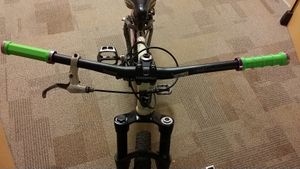
I attached both prints onto my bike after they were completed. This was an immensely satisfying project to design, prototype, and complete, and working with a $0.025 per gram filament cost, I worked out that each grip cost me $.52 to print. Given that the grips I had cost $20 on the market, this is savings of $19.5. The price markup from plastic, 3D-printed PLA to a market product is 3900%. Once again, I am very pleased. Here is the final product!
==Cufflink "Big Money" Project
Check it out! http://www.thingiverse.com/thing:2297214
Printed stuff[edit | edit source]
| Picture | Print # | Lessons Learned |
|---|---|---|
|
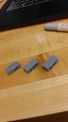
1,2, and 3 | How to get the print to stick |

|
4 | Replicating Jellybox parts (I'm pleased!) |

|
5 | Strength of Jellybox parts (printed using coarse material) |
| File:Clamp.PNG | 6 | Make a functioning material (3 parts!) |
| File:Rock Wall Hold.PNG | 7 | An assignment for class (10% infill, designed in Sketchup) |
