This page contains the work of University of Michigan - Dearborn students Tom Silka, Chris Marquette, Anthony Darkangelo, and Ryan Kiblawi. Their final design project for the Spring 2007 session of ME 379 Thermal-Fluids Lab is based on an experimental low-cost peak flow meter originally designed by Steve McCrosky.
Abstract[edit | edit source]
A Peak Flow Meter (PFM) was designed to achieve consistent exhalation results for the diagnosis and management of asthma. A calibration procedure was used to modify the flow meter to achieve consistency. To accomplish this, the behavioral characteristics of air, the working fluid, had to be understood. The air proved to be incompressible, with a steady laminar flow at constant properties in the fully developed region of a straight circular pipe. The Peak Flow Meter was fabricated using common materials, including PVC pipe, a mechanical pencil spring, a small piece of aluminum and a reciprocating saw blade. Calibration was conducted by the time in which it took to fully compress a raft pump with respect to pressure flow. The raft pump simulated the diaphragm in the human respiratory system and the flow chamber simulated lung capacity. Before the trials were started for the calibration process, the commercial PFM was attached to the raft pump first, to serve as a standard of comparison. The raft pump was compressed at a time recorded by a stop watch. A variety of trials were run in order to assign specific flow rates with respect to the time the stop-watch indicated. This procedure was performed again for our PFM. To calibrate our PFM, holes were drilled at the base and lower shaft of the PFM to alleviate pressure and simulate the performance of the commercial PFM. Trials were conducted until consistent resulted were achieved. Flow rates were then indicated on the saw blade by a color coded system.
Introduction[edit | edit source]
A Peak Flow Meter (PFM) is a portable, hand-held device that helps the user check how effectively their asthma is controlled by measuring the volumetric flow rate of the air that is exhaled. A variety of commercial Peak Flow Meter's can be seen below.
Figure 1: Commercial Peak Flow Meters A healthy person in their twenties can expect a peak flow rate of around 600 L/min. Patients with asthma will typically have a flow rate less than this, but will vary with their own health conditions. By using a peak flow meter every day and keeping track of the results, doctors will be able to see how a patients asthma is doing on a daily basis and will help determine what type of medical treatment is needed.
Objectives[edit | edit source]
Peak Flow Meters are useful at home and in clinics. This is especially true when a patient is able to see a change in the results before and after an in-office treatment. They would be able to notice any decline in the condition of their asthma and then relay the information to their doctor at their next appointment. Often a reduction of a person's maximum exhalation flow rate is a sign of a worsening health condition. The problem is that peak flow meters are not easily attainable everywhere people may need them. In many developing or remote areas, medical instruments like the peak flow meter are not easily found. This design project will concentrate on a simple Peak Flow Meter design which could be used by clinicians in developing or rural areas. The challenge is to design a device that can be built with supplies available in any small city in the world. This way, anyone who gets hold of the design could access all of the materials needed. The materials being used for the peak flow meter consist of PVC tubing for the body and a piece of aluminum used to measure the volumetric flow rate of the person's exhalation. The design should be standardized so that whoever builds it will get an accurate reading. The main challenge will not be the construction of the device itself, but rather its calibration. It must be assured that the low-cost peak flow meter is capable of repeatable results akin to production peak flow meters. Research has shown that there are no other similar efforts to design a low cost peak flow meter.
Experimental Apparatus[edit | edit source]
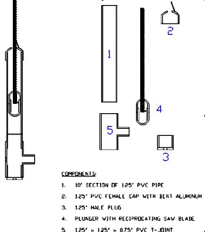
A peak flow meter consists of a hollow tube with a plunger inside that can travel freely. The part of the PFM that is blown into by a person should be perpendicular to the hollow tube that encases the plunger. The plunger is the device that is being displaced in proportion to the volumetric flow rate. Attached to the plunger is a mechanism that keeps the plunger at its maximum elevation in the hollow tube. In this design, a reciprocating saw blade on a spring loaded pivot point enables PFM measurement to take place.
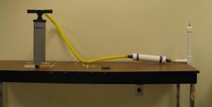
A hand operated air pump is connected to a flow chamber that is used to disperse an even flow into the PFM. When the pump handle is depressed, the standing air in the flow chamber is displaced, and moves into the peak flow meter. This process is designed to mimic that of a human blowing into the PFM, where the raft pump represents the diaphragm and the flow chamber simulates lung capacity.

As can be seen in Figure 4, to overcome the calibration challenge, our peak flow meter will be connected to the regulated air supply. This will simulate human lung power providing steady bursts of flow to calibrate the peak flow meter. Holes are drilled in a controlled pattern along the shaft to evenly release air pressure build-up underneath the plunging object inside the PVC pipe.
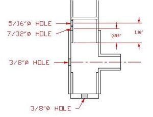
To create the Peak Flow Meter a 10 in section of a 1.25 in ID PVC tubing and a T-joint that has a 0.75 in female slip fitting on the perpendicular side will be used. A 1.25 in male plug is inserted on the bottom of the T-joint. The 0.75 in female slip fitting simulates the mouthpiece size on a commercial PFM. A 0.75 in female end cap smoothly fits inside the 1.25 in PVC this is how the plunger was formulated. The plunger consists of two 0.75 in caps attached with a 1 in section of 0.75 in pipe. At the top of the PFM there is a 1.25 in female cap with a slot cut in it. The slot serves as an access way for the reciprocating saw blade to slide through. A piece of aluminum is bent to match the angle of the teeth on the reciprocating saw blade. A 0.125 in hole is drilled through on one of the caps just before the convex dome. A pin is inserted through this hole to hold the reciprocating saw blade. A slot is cut in the cap of the plug, allowing the end of the spring loaded reciprocating saw blade to pivot about the pin inside the cap. The compression spring was taken from a retractable pen. This spring was super-glued perpendicular to the blade edge. The spring supplies enough resistance to press the blade against the aluminum catch device at the top of the PFM. A 0.125 in hole is drilled 1 in from the bottom of the 10 in section of PVC pipe and a pin is inserted. The purpose of this pin is to allow the plunger to start at a consistent level every time the plunger is reset. The first hole that needs to be drilled in the 10 in section of pipe has a 5/16 in diameter and is located 1.16 in from the bottom of the pipe. The second hole has a 7/32 in diameter and is located 0.84 in from the bottom of the pipe. A 3/8 in diameter hole is drilled in the middle of the T-joint directly across from the 0.75 in female opening. The last hole also has a 3/8 in diameter that is located on the center of the bottom 1.25 in male plug. The figure below shows a cross sectional view of the location where the holes should be drilled.
A commercial raft pump was modified and fitted with a stop watch to allow for precise timing of air flow. The setup is as follows: A standard stopwatch was disassembled, and shielded wires were soldered to the start/stop button's metal activation surfaces. The wires lead to two simple buttons. One of the buttons is attached to the handle of the pump, and another was inserted into the bottom surface of the inside of the pump. When the user begins to push down on the handle, the handle button is pressed. Upon reaching the bottom of the plunger's travel, it depresses the button in the bottom of the pump and automatically stops the stopwatch. The reset button of the stopwatch was retained so that the time can be reset and multiple trials can be run.
A raft pump was connected via 0.75" tubing to a device known as a flow chamber. The flow chamber consists of two 1" by 1.25" adapters connected with an 8" section of 2" PVC pipe. On each end of the flow chamber, 1" male hose adapters were threaded into the flow chamber making certain to use Teflon tape to prevent any sort of air leakage.
Experimental Procedure[edit | edit source]
Before the trials were started for the calibration process it was verified that the raft pump tubing and all PVC joints were securely connected, and the stop-watch is zeroed out. To serve as a standard of comparison, the commercial PFM was attached to the raft pump first. The setup was placed on a table making certain that none of the holes were obstructed. Prior to compressing the pump it was assured the plunging device on the PFM was reset to the zero position. The raft pump was compressed at a time recorded by the stop watch. To activate the stop-watch the red handle button was pressed simultaneously as the handle to the raft pump was being compressed. The handle was completely pressed to stop the time on the stop-watch. The compressed air then travels into the flow chamber to create a constant volumetric flow rate to the PFM. A variety of trials were run in order to assign specific flow rates with respect to the time the timer indicated. This procedure was performed again for the designed PFM. To calibrate the deisgned PFM, specific size holes were drilled at the base and lower shaft of the PFM to alleviate pressure and simulate the performance of the commercial PFM. Trials were conducted until consistent results were achieved. The midpoint was then noted on the reciprocating saw blade. Referencing the standard data that was achieved in the trials, a correlation was achieved for flow rate. Flow rates were then indicated on the saw blade by means of a color coded system.
Conclusions[edit | edit source]
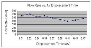
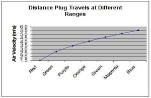
It can confidently be concluded that this design project was a success. From the inception of the project until the end, we found ourselves utilizing multiple skills acquired over the years spent here at The University of Michigan – Dearborn. A Peak Flow meter was designed with very basic materials, and was able to be calibrated to replicate the flow results of a commercial flow meter. A large obstacle was being mindful of the budget in the creation of the Peak Flow Meter. As can be inferred from our Budget, seen in the Appendix, our PFM with out calibration instruments, totaled to be $7.65, which is less than half the price of the cheapest PFM out on the market.
Although we did achieve accurate results that were consistent with that of the commercial peak flow meter, our design did present us with some unexpected inaccuracies. Fortunately, these turned out to be present at the very high and very low range of peak flow readings. Our major flow measurement inaccuracies stemmed from the design of the flow indicator. The flow indicator (reciprocating saw blade) is lightly pressed against the aluminum stopper by a small spring. At most flow values, the spring does not have an appreciable effect on the operation of the device. However, at higher flow values, the spring is stretched further and more force is put on the indicator. This load was not initially accounted for, and thus presents an inaccuracy. Fortunately, someone capable of achieving an upper flow value (> 700 L/min) is not expected to have problems which would entail the regular usage of a peak flow meter. Also presenting a source of inaccuracy was the weight of the plunger itself. At lower flow values, the force of the air pushing against the plunger is not sufficient for the generation of accurate, repeatable results. However, it is likely that a person achieving a peak flow of less than 350 L/min will require medical attention beyond the scope of home peak flow meters.