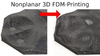
Nonplanar printing, in 3d printing, refers to printing parts that use layers where the nozzle is moved in both the [x,y] and z axes to create curved surfaces, as opposed to using discrete layers in the z axis. This allows very smooth layers to be generated, especially in low-angle geometry where stair-stepping is apparent. An example is shown to the right.

Model and Extruder Geometry[edit | edit source]
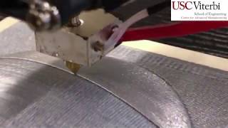
A printer with 4 or 5 axes, where the nozzle can be kept fully tangent to the print surface, is ideal, but a 3-axis printer can be used. The most appropriate geometry for nonplanar slicing with traditional, unmodified hot ends (small flat on bottom, 90 degree angle) is shallow, low-angle curved surfaces. End effectors that have few to no obstructions around the hot end are ideal, as they have less geometry that could collide with the part being printed.
Tutorial using slic3r-nonplanar by the University of Hamburg[edit | edit source]
The University of Hamburg is developing an open-source, modified release of Slic3r that includes a method for non-planar slicing.[1] This can be used to generate gcode for nonplanar printing on any printer. Linked at the bottom of this page is an additional tutorial by the youtube channel "Teaching Tech" that includes instructions on modifying print heads for compatibility. This tutorial will assume you're using something like an AthenaII that has a very clear hotend.
This tutorial assumes you already know how to use slic3r, or another advanced slicing program. Myriad tutorials are available for this software, as well as documentation within the software.
- Currently, the nonplanar slic3r build requires compiling from source. If you're running a Linux system, specifically one using
aptfor package management, the instructions on the README page will work without modification. On a Windows or other system, you'll either need to run debian or a similar distribution in a virtual machine, or install the Windows subsystem for Linux as well as an X server like Xming. Instructions for this are available thanks to a comment by Lorgie1984 on the github issues page, utilizing tutorials from Microsoft and HowToGeek. - With a Linux system, or the Windows subsystem for Linux, follow the instructions on the README page of the nonplanar branch to build slic3r. Note that on Windows, Xming must be running, and it may be necessary to launch slicer with
DISPLAY=:0prepended to the perl command in order to get the GUI to launch. - If you already use slic3r to slice your parts for printing, you can export the settings using
File -> Export Config...from your usual slic3r installation and import it usingFile -> Import Config...in the nonplanar build. Otherwise, set up slicer usingSettings -> Printer Settings..., filament, and print settings. - Load an STL file for printing, with an appropriate surface for nonplanar slicing. The top 1/4 of a sphere is a good example. Note: on WSL, you can access files in the windows filesystem by navigating to
/mnt/and opening the drive letter of interest (cforC:/, for example). - The settings for nonplanar slicing are located in
Settings -> Print Settings... -> Layers and perimeters, under the "nonplanar layers" section. Three options are available: "Use nonplanar layers", "Maximum nonplanar angle", and "Maximum nonplanar height". The latter two settings change the geometry used for collision detection. - The collision detection seems to be extremely conservative. If either setting is set too low, the slicer will not generate nonplanar layers. It may be necessary to "force" the generation of nonplanar layers by setting the maximum angle to >40 degrees and the maximum height to >10 mm. However, this means that the end effector may be at risk of colliding with geometry in the part. Reasonable judgement and experience must be applied to determine if this is an issue.
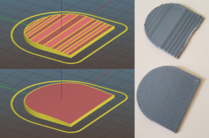
Planar (top) and Nonplanar (bottom) toolpath and part. Note smoothness and lack of stair stepping effect. - The slicing results can be checked by previewing the toolpath. Iteration will be necessary to generate acceptable toolpaths for printing.
- Certain geometry, namely small parts that are on the order of the layer height (<5mm height) can cause the nonplanar layers to generate oddly, creating toolpaths that intersect with already deposited material, or even toolpaths that drive the end effector below the print bed (!). Again, exercise judgement. Also note that for the AthenaII's this will simply result in the end effector/guide rods popping off the magnets so you can be more aggressive than if you are on a rigid machine.
- Once an acceptable toolpath is generated, save the gcode and load it onto your printer. Note that the print time estimated by the printer may overestimate by a large factor; in the part shown to the right, the printer estimated around 1 hour for a print that took 12 minutes to complete.
- Print the model - but stay close by! Observe the execution, and make sure the geometry works and the end effector does not run into the print or bed.