Extra Low voltage power supply

This article assumes that the input for the desired low voltage power supply is alternating current (AC) and that the power supply will be outputting low voltage direct current (DC). If you have a higher voltage direct current source and require a lower voltage, you will want to use a DC to DC converterW. If you have a main voltage alternating current source that you would like to use at a lower voltage, you will want to use a transformerW.
You can connect the Low voltage power supply with:
Links Low voltage connection basics
Using a PC power supply[edit | edit source]


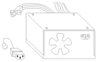
Typical PC power supplies have maximum output power ratings ranging from 300 watts to 500 watts and contain the needed circuitry to convert alternating current (at 110V or 220V) into direct current at a lower potential (5V and 12V) for your low voltage needs.
Computer components require a clean (ripple free) power supply, when the voltage of either the 12V or 5V (in some cases 3.3 is also provided) begins to drop below or above this point, computer crashes can become more frequent. Your local computer repair shop may have several "bad" power supplies on hand that you could acquire for a very low price.
Tools:
- screwdriver
- cable cutter (optional)
Materials:
- Old computer power supply
- Electric connection block (optional)
One benefit of using an old computer power supply as your power supply is that the enclosure will already be grounded (as long as you use a three prong grounded outlet) and there will be minimal risk of shock to the user.
The plug houses connections to both the 5V and 12V rails and is called a Molex connectorW . If you want to clean up the appearance of your power supply feel free to cut the other wires and plugs - but be sure that there is no possibility of any contact between bare wires as this can cause a short circuit and damage your power supply.
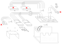
You may want to retain the ON/OFF switch of your power supply. However, if you want your power supply to continuously run while plugged in, you can cut the leads of the switch and the leads of the AC input and connect them both together using the connection block as shown in the third image.
Please note that the power supply in this image is an older AT type. The supply you have acquired may be a of different form factor. Therefore, it may be best not to remove wires or otherwise modify the power supply. In any case, the molex connection is fairly standard and should be found on almost all types. If you have any doubts as to which connections can provide 12V or 5V, a multimeterW will be of much help. Once you have identified wires that provide 12V or 5V, you may want to remove the molex plug and screw the wires into a connection block. Be sure to label the voltage and polarity of each terminal on the connection block if you choose to do so.
Using a Rectifier Circuit Directly[edit | edit source]
If you have an AC source but require DC your simplest option will be to create a rectifier circuit.
If you are dealing with a high voltage AC input you will first want to use a transformer to drop the voltage. A transformer is made up of two wire coils, and when an alternating current passes through the primary coil a voltage is produced in the secondary coil by means of induction. The ratio of turns in the primary and secondary coils corresponds directly to the ratio of the voltage present in the primary and secondary coils.
Half-Wave Rectifier[edit | edit source]
By placing a diode in series with the transformer and load, current is allowed to travel the circuit in only one direction. The voltage across you load will be positive, but only half of the current available will be available. You will also see a voltage drop of around 0.7V across the diode. Because this circuit removes the negative (or positive depending on the orientation of the diode) portion of the AC input wave it is called a half-wave rectifier.
Full-Wave Rectifier (Full-Wave Bridge)[edit | edit source]
A full-wave rectifier circuit uses three more diodes than a half-wave rectifier. The diode bridge found in this circuit allows the input current to flow in the same direction through the load. Rather than just allowing one voltage polarity to pass, the full-wave bridge reverses the polarity of the negative component of the input wave. Since each half of the AC wave must pass through two diodes a voltage drop of around 1.4V will be seen.
Improving Your Rectifier Circuit[edit | edit source]
A voltage drop of 0.7V or 1.4V is quite large if you are dealing with 5V or 12V. Chances are your transformer will output a voltage at a higher potential anyway. In this case you will want to place a voltage regulatorW in series with your source to produce the desired voltage. You may also want to use a capacitor to filter the ripples out of your power supply's output current.

