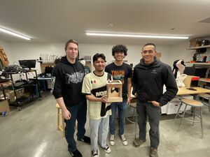
We are the Thermodynamic Outlaws, the designers and manufactures of the Cal Poly Humboldt Claw Machine. The CPH Claw Machine, built in Spring 2024, is primarily operated by a pulley system that two users control to maneuver the claw in the x-z plane. The claw is robotic, and a user must operate the control board to move the claw in the y-axis, as well as close and open it. The CPH Claw Machine is intended for potential incoming students that attend Cal Poly Humboldt's preview events.
Background[edit | edit source]
This project is for Cal Poly Humboldt's ENGR 205: Intro to Design course in Spring 2024. This course is taught by Lonny Grafman and Qualla Ketchum. Our team's client for this project is the head of Cal Poly Humboldt's school of engineering, Dr. Eileen Cashman. The project will be on display for interaction during preview events held for future college students that may be interested in Humboldt. The specific given prompt for our team to focus our project around was an interactive model of mechanical engineering applications.
Problem statement[edit | edit source]
The objective of the Cal Poly Humboldt Claw Machine is to invoke thought and interest in potential incoming students regarding Cal Poly Humboldt's school of engineering, while remaining consistent with the school's core values.
Criteria[edit | edit source]
Below is the criteria defined for the project. The weight was determined by the client's representative, Dr. Eileen Cashman. The purpose of this weight is to ensure the team prioritizes the client's needs and wants.
| Criteria | Description | Weight (1-10) |
|---|---|---|
| Interactivity | The quality and level of the inclusion of a simple and intuitive feature(s) that allows hands-on interaction, improving the overall user experience with the design. | 10 |
| Safety | The protection from or unlikeliness of physical harm to anybody interacting with, or near the product. | 10 |
| Educational | The quality of the demonstration of complicated engineering concepts in a simple way, avoiding confusion and making it easy for the intended audience to understand and appreciate. | 10 |
| Aesthetics | The possession of an aesthetically appealing and engaging appearance that successfully captures the attention and interest of the target audience, motivating them to further explore and interact with the product. | 9 |
| Longevity | The cost and frequency of repairs and maintenance using accessible resources and basic technical skills. | 8 |
| Weight and Size | The level of portability and ease of carrying or moving by a single person. | 5 |
| Cost | The total cost of materials. | 3 |
| Construction Time | Time for the client and/or customers to set up for use. | 3 |
Prototyping[edit | edit source]
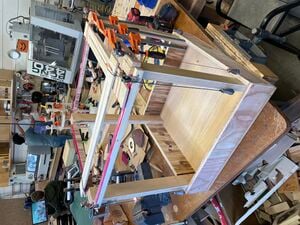
We designed and built two prototypes prior to the finalization of the product. The was scaled down to roughly 1/3 of the final design's dimensions and was built to both demonstrate the manual maneuver of the claw in the x-z plane was going to work, as well as show our client what we generally envision the final product to look like. The claw constructed for this prototype was not functional and was purely for visual purposes. On this prototype were wires wrapped around two popsicle sticks that, by pulling on the wires, would slide across the top of the frame. The intersection point of these two popsicle sticks is where the claw hung from. This design allowed the claw to be moved anywhere in the x-z plane but did not allow for movement in the y-direction nor the opening or closing of the claw. The general design was to be implemented in the second prototype, as the frame and sliders design was deemed a success. Photos of the first prototype can be seen in the bottom right.


The second prototype was significantly more similar to the final product. It was to scale, and included a fully functional pulley system that connected the sliders to handles and weights. When pulling down one of the two handles, the slider attached to the handle moves towards the user. When the user lets go of the handle, the weights on the opposite side of the user pull the slider away from the user and raise the handle. There are also tracks installed on the top of the frame to allow for less degradation and friction that would be c caused by wood-on-wood contact. This system is what allowed for the intersection point to exist at any location along the x-z plane. There was an attempt to create a claw operated by a pulley system, but it was unnecessarily complex and visually unattractive, so we decided to consider it a failure and pursued a robotic claw. A robotic claw was only achieved during the construction of the final design. The second prototype only had a couple flaws besides the claw mechanism complications. The tracks were not satisfactory, as there was still significant friction between the sliders and the track. This was kept in mind during the construction of the final product. Upon examination of the second prototype, the client requested that we make the product more portable. This led us to turn the final product into a claw machine wagon, with four wheels on the bottom, two of which could lock, preventing the claw machine from moving whatsoever. We also decided to install a rope on the final product to allow for easier transportation. A photo of the second prototype can be seen in the bottom right, just below the photos of the first prototype.
Final product[edit | edit source]
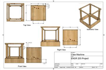
The final product design, being a functional claw machine, is made of many complex components. The Cal Poly Humboldt Claw Machine’s base is about 2ft by 2ft and is a little over two feet tall. The frame is completely made from wood. The claw is maneuvered in the flat x-z plane via a manual pulley system that is controlled by two users, with one handle each. The handles are attached to cord that, through the pulley system, lead to the sliders that the claw is attached to. These sliders are also made from wood. There are small weights on the opposite side of the two users that pull the sliders to the opposing side, which also raises the handles, when the users let go of the handles. This is all connected via a pulley system. There is also a railway system that is installed on the top of the frame that allows for low friction when the sliders move.
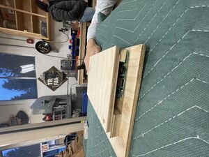
The claw mechanism is installed on the intersection point between the two sliders. The claw mechanism is connected to a Raspberry Pi computer, which is programmed to raise, lower, close, and open the claw through buttons on a wooden control board placed next to the claw machine. The claw was 3D printed and is made of plastic. Servo motors are responsible for closing, opening, lowering, and raising the claw and are installed in the claw mechanism. The wiring that connects the computer to the claw mechanism is discreetly run along the frame. The faculty running the claw machine can access the Raspberry Pi’s functions via a touchscreen provided that is placed next to the control board.
Wheels are also installed on the bottom of the claw machine, two of which lock in place, preventing the claw machine from moving whatsoever. There is rope attached to the frame of the claw machine. Both inclusions are for whoever may be transporting the Cal Poly Humboldt Claw Machine.
Construction[edit | edit source]
In this section we describe how to construct the Cal Poly Humboldt Claw Machine.
To begin, you need to cut out wood as seen in the frame drawing seen in the bottom right. Then, you must put all of the wood together to construct the frame as seen in the same photo in the bottom right. After the frame is constructed, cut out sliders to match those in the second prototype as seen in the photo to the right. Before putting the sliders to use, you need to 3D print a set of tracks to glue (using super glue) on the underside of the ends of the sliders and the top of the frame. Once the tracks are glued on, you may place the sliders onto the frame of the product. Wrap two cords around each end of each slider. The two cords on each end should be facing opposite directions. For each slider: one set of cords should lead to two pulleys on opposite ends of the claw machine. The cords should go through the pulley, leading to a small weight on each side that the cords are tied to. On the other side of the claw machine, the other set of cord goes through another pair of pulleys that are on the two corners of the claw machine frame that the cord is heading towards. The cord goes through the pulleys, down a couple inches towards two nails sticking out of the frame (pointing away from the claw machine) and then bends around the nails, changing its path by 90 degrees and begins heading towards a double pulley in the middle of the frame in which the two ends of cord meet. As the cords go exit the double pulley and head straight down, tie the cord together around a single handle. Doing this twice, with two separate cord sets, creates a fully functional pulley system. To ensure ease of transportation, attach four wheels underneath the frame base, two of which must lock to prevent the claw machine from moving. Also attach a rope to the frame of the claw machine for pulling around during transportation.
For the claw mechanism, start by 3D printing a claw that has a place to insert a servo motor. Put the claw and servo motor together, and then use basic coding skills to code the servo motor to open and close the claw with the click of a button. Get another servo motor with a string attached to rig on above the slider intersection point. Use basic coding skills to be able to free and retract the string. Then place put the string through the intersection point and attach the end of the string to the claw. Make sure all the wires that connect the Raspberry Pi and servo motors run safely along the frame of the claw machine.
For the control board, build one out of wood as seen in the photo to the right. The Raspberry Pi is to be placed inside the control board, with the buttons placed on top. You have constructed the Cal Poly Humboldt Claw Machine.

Bill of materials[edit | edit source]
Description of costs. Does not include items that were given to us, as the prices of said items are uncertain.
| Item | Amount | Cost per unit | Total |
|---|---|---|---|
| Pulley | 6 | USD 4.99 | USD 29.94 |
| Weight Set | 2 | USD 6.99 | USD 13.98 |
| Raspberry Pi | 1 | USD 59.95 | USD 59.95 |
| Touchscreen — For the Raspberry Pi | 1 | USD 52.99 | USD 52.99 |
| 4" Caster Wheel | 2 | USD 15.19 | USD 30.38 |
| 4" Swivel Locking Caster Wheel | 2 | USD 18.99 | USD 37.98 |
| Super Glue | 1 | USD 8.99 | USD 8.99 |
| Micro SD Card | 1 | USD 24.99 | USD 24.99 |
| Grand total | USD 259.2EUR 222.91 <br />GBP 189.22 <br />CAD 321.41 <br />MXN 5,404.32 <br />INR 19,401.12 <br /> | ||
Operation[edit | edit source]
The following steps explain how to operate the Cal Poly Humboldt Claw Machine.
After transporting the product and setting it in place, lock the wheels to ensure the CPH Claw Machine cannot move.
Turn on the Raspberry Pi computer located inside the control board, then proceed to the coding program and run the system.
The CPH Claw Machine is now ready for use! To close, open, lower, and raise the claw, use the bottoms located on the control board. To move the claw horizontally, pull down the handles on the claw machine.
Maintenance[edit | edit source]
There are no needed actions for maintenance, other than possibly cleaning off dust when being taken out of storage and has been untouched for a significant amount of time (i.e. months). Whoever is taking the Cal Poly Humboldt Claw Machine out of storage may wipe it down to remove any collected dust or other small debris. Otherwise, maintenance is not necessary for this product. There are no parts involved that require any actions for maintenance.
Maintenance schedule[edit | edit source]
Maintenance schedule for the Cal Poly Humboldt Claw Machine.
- Daily
- N/A
- Weekly
- N/A
- Monthly
- N/A
- Yearly
- Wipe off dust and other small debris.
Conclusion[edit | edit source]
Testing results[edit | edit source]
Describe the testing results. (N/A)
Discussion[edit | edit source]
Discuss the testing results. (N/A)
Lessons learned[edit | edit source]
Discuss lessons were learned during this project and what you would do different next time. (N/A)
Next steps[edit | edit source]
Discuss any next steps for the project as it goes on into the future. (N/A)
Troubleshooting[edit | edit source]
Below is a table that demonstrates how to troubleshoot basic operation of the Cal Poly Humboldt Claw Machine.
| Problem | Suggestion |
|---|---|
| Sliders having trouble moving | Make sure string is not caught in side of pulley |
| Claw not reacting to control board interactions | Make sure computer is turned on and code is running |
Team[edit | edit source]
Listed below are the members of the Thermodynamic Outlaws, a team established in the Spring 2024 semester in Engineering 205: Introduction to Design at Cal Poly Humboldt.
References[edit | edit source]