
The Wirtz Pump display project was designed by team Intrepid Hobbits for the Department of Engineering on Cal Poly Humboldt's campus in Arcata, California. The design was created during the Spring 2024 semester for Cal Poly Humboldt's ENGR205 class: Introduction to Design. This project was created to attract prospective engineers to Cal Poly Humboldt's engineering program.
Background[edit | edit source]
The project was introduced by the team's respective client the Department Chair of the School of Engineering Eileen Cashman. The Wirtz pump was designed to serve as a visual at outreach events or whenever needed for the engineering program.
Problem statement[edit | edit source]
The objective of this project is to provide the engineering department with a table-top display that can be used to showcase Humboldt engineering values during outreach events. The design should be educational,
Criteria[edit | edit source]
During the problem analysis phase of the design process, the Intrepid Hobbits came up with a set of criteria that met the client's needs. The team then worked with the client to weigh the importance of the criteria relative to each other ranked on a 1-10 scale.
| Criteria | Constraints | Weight |
| Size | The project must be able to on or around table | 6 |
| Cost | Must be under $400 | 3 |
| Build Time | The final product must be built within 6 weeks | 10 |
| Aesthetics | Must be visually appealing | 8 |
| Cal Poly Humboldt Values | The project must represent environmental sustainability and safety. | 9 |
| Durability | The project must be able to withstand multiple uses per year for multiple years | 8 |
Prototyping[edit | edit source]
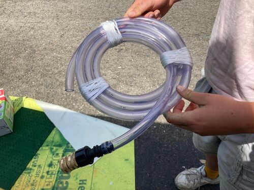
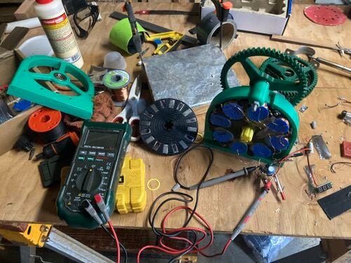
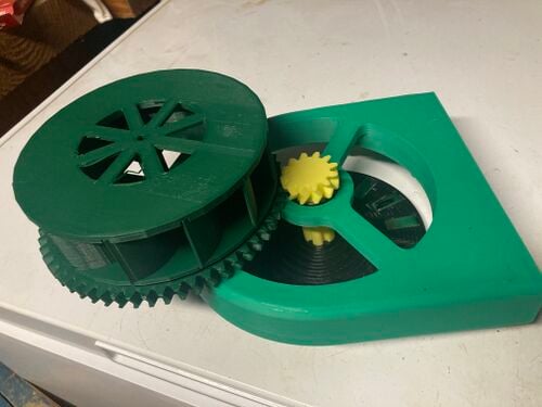
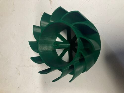
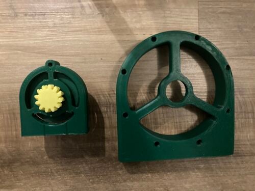
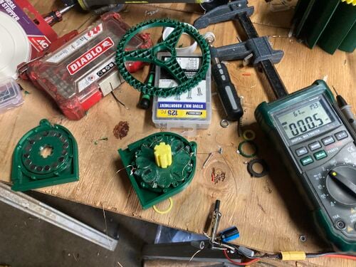
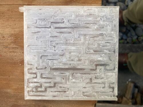
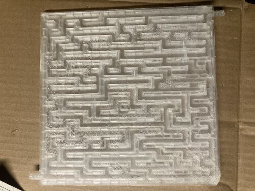
In order to meet our Criteria we decided to design a system that would utilize a hand powered pump to move water up a vertical distance to be drained onto track where it would turn a wheel attached to a small generator to produce electricity, then be returned back to the reservoir to reenter the cycle. We decided on utilizing a Wirtz pump to move the water and adapting a design for a hand crank generator to generate the electricity. Constructing the Wirtz pump we had to produce a coupling for our vinyl tubing that would allow for one end of it to rotate while the other stays stationary, and be water/ air tight. We also learned that the number of coils that the Wirtz pump has corresponds to the maximum a higher vertical distance it can pump (more coils equal more height).The Hand crank generator was a design we found online, it utilized 3-d printing and involved building electrical generation parts from magnets, wire and bearings. The generator was able to produce a decent amount of power but we found that the force of the water could not turn the wheel we attached the generator to, this lead to manipulation of the generator design to shrink it down and reduce its weight while maximizing the amount of water the water wheel can accommodate. A second mini version of the generator was produced but it was barely able to produce a volt. This lead us to abandon the idea of generating electricity and to just focus on the Wirtz pump output, we decided on demonstrating the Wirtz pump's ability to manipulate the flow of water. The water maze shows how in pressurized system a Wirtz pump can change the direction of water flow by turning the pump in the reverse direction, water will actually travel backward in the maze.
- Sample gallery
-
-
-
-
-
-
-
-
-
-
-
-


Final product[edit | edit source]


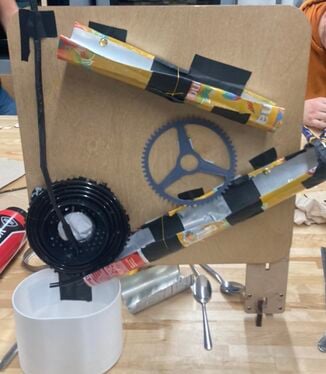
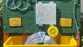
Our final product includes a Wirtz pump built onto a rectangular reservoir, directly above a peg board is attached to the reservoir utilizing old growth recycled redwood for its supports. when the handle is rotated in the clockwise direction water moves up the vertical tube and forward through the system of vinyl tubing until at its end it encounters the entrance to the water maze. The water will make its way through he maze until it reaches the end where it will fall onto the water wheel directly below and turn it, as an example of how this system could be used to generate useful output if its size were scaled up. After turning the wheel the water will fall back into the reservoir where it can be pumped back into the system again. Upon turning the Wirtz pump in the counterclockwise direction water moves in the reverse direction through the system and exits out of the entrance of the pump.
Construction[edit | edit source]
The Frame was constructed out of old growth recycled redwood and attached with countersunk 2" torx screws, the back leg is hinged with a recycled cabinet door hinge with a 30 degree bevel cut into it at the bottom to help stabilize the backboard, which is a standard peg board that is painted with Rust oleum spray paint and a coat of shellac to help protect it from water damage. 1" holes were drilled out of the located center of the reservoir on each of its long faces 2" down from the top. The Frame was then attached to the reservoir via a gasqueted screw running from the outside into the redwood, the rotational joint was then assembled with the Ice box elbow on the outside of the back of the reservoir and the rotational hose coupling on the inside of the reservoir, and the stabilization bracket was installed on the ice box elbow to prevent it from rotating. The 1/4" vinyl tubing is then connected to the ice box elbow utilizing Teflon tape and running through the vinyl tubing stabilization bracket and attached to the peg board via the floral wire in the desired path. The water maze and water wheel are then placed at the appropriate positions such that the water will interact with them as intended. The Wirtz pump was assembled by taking 1/2" I.D vinyl tubing and wrapping it around itself to form a number of coils, which are then tied together using twine and to its frame which is made of two sticks of Douglas Fir 1"x2"x10" painted and finished with spray on shellac with a 7/8" hole drilled out of its center. The Wirtz pump was then installed first by attaching the output end of the pump to the rotational coupling via a 1/2" I.D vinyl tubing to hose adapter coupling utilizing Teflon tape. 1" O.D vinyl tubing was run through the hole in the front of the reservoir and through the hole in the center of our Wirtz pump frame where it fits snugly, then the handle and shaft parts were attached via gasqueted screws to finish off the assembly.
- Sample gallery
Video instructions[edit | edit source]
Operating the Wirtz pump is an easy process that involves turning a handle to allow the pump to spin.
Bill of materials[edit | edit source]
This is a table of all of the materials used in the final project. The costs listed are the current prices for each item and the price paid.
| Item | Amount | Cost per unit | Total |
|---|---|---|---|
| Gorilla Glue | 2 | USD 8.62 | USD 17.24 |
| Floral Wire | 1 | USD 7.80 | USD 7.80 |
| Nylon Twine | 1 | USD 6.82 | USD 6.82 |
| Shellac Spray | 1 | USD 13.02 | USD 13.02 |
| Phillip Screws and Flat Washers | 6 | USD 0.18 | USD 1.08 |
| Brass 3/4" Swivel FHT | 1 | USD 5.15 | USD 5.15 |
| Brass 3/4" MHT | 2 | USD 5.45 | USD 10.90 |
| Hose adapter | 2 | USD 1.95 | USD 3.90 |
| Qc hose adapter to 1/4" | 1 | USD 9.17 | USD 9.17 |
| 3/16" I.D. vinyl tubing | 10 | USD 0.15 | USD 1.50 |
| Ice Maker elbow | 1 | USD 7.80 | USD 7.80 |
| Handle Hardware | 1 | USD 6.12 | USD 6.12 |
| Teflon tape | 1 | USD 1.75 | USD 1.75 |
| Tote bin — HSU purchased | 1 | USD 0.00 | USD 0.00 |
| 1/2' I.D vinyl tubing — HSU purchased | 1 | USD 0.00 | USD 0.00 |
| Spray Paint (Rust oleum) — yellow, green | 2 | USD 7.35 | USD 14.70 |
| peg board — HSU purchased | 1 | USD 0.00 | USD 0.00 |
| Grand total | USD 106.95EUR 91.98 <br />GBP 78.07 <br />CAD 132.62 <br />MXN 2,229.91 <br />INR 8,005.21 <br /> | ||
Operation[edit | edit source]
There are a couple of simple steps necessary in order to get the Wirtz Pump to operate for every use.

set reservoir in the location of operation, set up and attach the backboard to the reservoir via gasqueted screws

attach vinyl tubing to the ice box elbow located in the back of the reservoir using pliers, then fill reservoir with water until water lever just touches the redwood. once filled just turn the handle to operate, clockwise moves the water forward counterclockwise moves it in reverse.
Maintenance[edit | edit source]
This project was designed to be low maintenance and durable. Most of the components used will last many years and uses; however, parts tend to wear down over time. The team predicted what parts could break in the future, and also included the minimal maintenance needed for the project per use.
Maintenance schedule[edit | edit source]
- Per Use
- Check the joints for leaks and tighten wherever necessary
- Every few years
- Replace the compression bead if broken (due to overtightening or continuous wear)
Conclusion[edit | edit source]
Testing results[edit | edit source]
The Wirtz pump design successfully uses human power to display the pump's ability to move water vertically, and manipulate the flow of water to move forward and backward through a system. The original tests to use the water to spin a water wheel that would generate electricity failed and the team ran out of time to come up with a new solution.
Discussion[edit | edit source]
In order to test the Wirtz pump, there were many variables that could cause implications to the success of the pump. Some of the variables were leaky joints, lack of air pressure, amount of tube coils, spacing of coils, speed of the pump turning, and a combination of different factors at once. Through testing of the Wirtz pump, the team realized that the vertical distance the water can move is limited by the number of coils in the pump. Also, the speed of the rotation of the pump needs to be slow enough to allow the air water exchange to take place in the coils.
Lessons learned[edit | edit source]
The biggest lesson the team learned was to fully understand the client's needs by continuous communication before sizing components and buying materials. The team spent a lot of time and money creating prototypes that were much too big for the client's needs.
Next steps[edit | edit source]
One possibility for the future of this project could be to design a rotational joint for the pump that is more precise and easily implemented, instead of bulky and inconvenient. Another step could be to find a way to generate electricity through hydropower after pumping the water, which could require sizing up the pump and using more water.
Troubleshooting[edit | edit source]
| Problem | Suggestion |
|---|---|
| A 3D printed piece broke or cracked | Reprint it using the STL files saved on a flash drive in the Makerspace |
| There is a leak in the rotational joints | Tighten the joints with pliers or a wrench. If that doesn't work, then dismantle the joints and replace the Teflon tape. |
| The string attatching the Wirtz Pump tubes together becomes loose | Retie the string or hot glue the string to the tubes to keep it together |
Team[edit | edit source]
References[edit | edit source]