Original file (1,163 × 539 pixels, file size: 47 KB, MIME type: image/png)
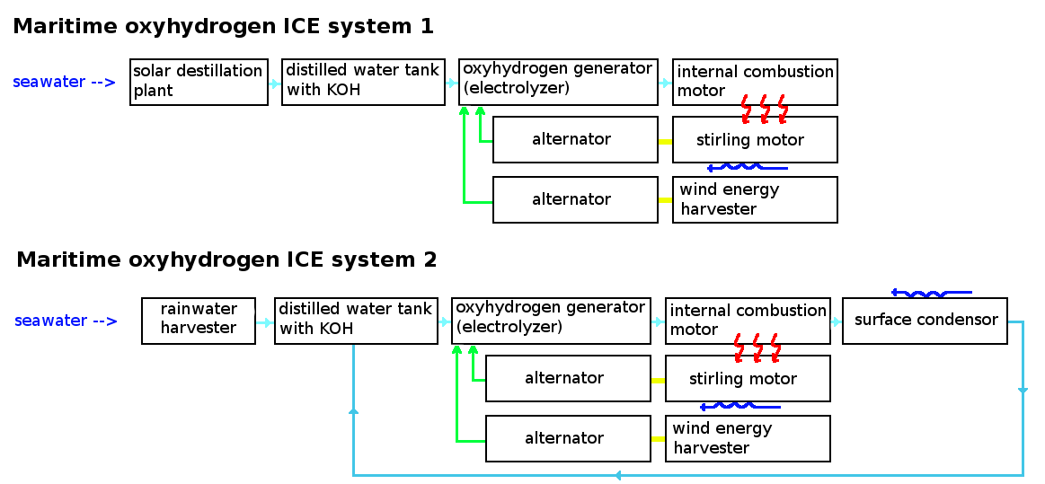
A schematic showing the setup of a maritime internal combustion engine system. The red arrows indicate heat transfer (done using heat exchangers using oil), the dark blue arrows indicate cold transfer (done using cooling with seawater); the yellow indicates that there is a mechanical linkage; the green indicates that 2 parts are connected electrically (using electric wires). In the second system, the used oxyhydrogen gas is not released to the atmosphere but cooled using seawater and redirected to the distilled water tank.
The systems presented here could be used for the conversion of boats. Finally, note that besides using solar water distillation, reverse osmosis systems too could be used; however these do require electricity, reducing the efficiency of the system somewhat.
File history
Click on a date/time to view the file as it appeared at that time.
| Date/Time | Thumbnail | Dimensions | User | Comment | |
|---|---|---|---|---|---|
| current | 12:28, 3 August 2011 | | 1,163 × 539 (47 KB) | KVDP (talk | contribs) | corrected small mistake |
| 12:26, 3 August 2011 |  | 1,163 × 539 (47 KB) | KVDP (talk | contribs) | A schematic showing the setup of a maritime internal combustion engine system. The red arrows indicate heat transfer (done using heat exchangers using oil), the dark blue arrows indicate cold transfer (done using cooling with seawater); the yellow indicat |
You cannot overwrite this file.
File usage
The following page uses this file: