Heat_recovery_ventilation_schematic.png (480 × 426 pixels, file size: 8 KB, MIME type: image/png)
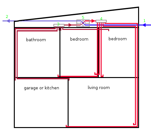
Schematic of a heat recovery ventilation system in a house.
- 1: fresh air (from outside the house); can be either cold or hot; must atleast be o°C or above; at days this is not reached the air entering via this pipe must be heated, see here.
- 2: cold stale air (from inside the house). This cold, humid and smelly air is vented outside the house
- 3: manifold for pipes conveying warm stale air (from inside the house); the manifold equalises the temperature of all rooms
- 4: manifold for pipes conveying purified (no longer humid, smelly) warm air (from inside the house); the manifold equalises the temperature of all rooms
- 5: 'Counter current) air to air heat exchanger; for a close-up, see Counter_current_air_to_air_heat_exchanger.png
Note that inside the counter current air-to-air heat exchanger, filters are present to remove smells (e.g. from the garage or kitchen, ...) and water (to reduce moisture content of the air; e.g. from air sucked in from outside the house and from rooms such as the laundry room, bathroom, ...). There are also 2 fans present inside the counter current air-to-air heat exchanger.
The schematic was made based on the images at http://www.genvex.co.uk/images/p9.gif and http://commons.wikimedia.org/wiki/File:Heat_exchanger.jpg
File history
Click on a date/time to view the file as it appeared at that time.
| Date/Time | Thumbnail | Dimensions | User | Comment | |
|---|---|---|---|---|---|
| current | 12:12, 18 March 2013 | | 480 × 426 (8 KB) | KVDP (talk | contribs) | Schematic of a heat recovery ventilation system in a house. *1: fresh air (from outside the house); can be either cold or hot; must atleast be o°C or above; at days this is not reached the air entering via this pipe must be heated, see [http://en.wikipe |
You cannot overwrite this file.
File usage
The following page uses this file: