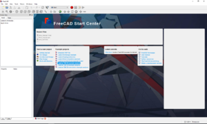
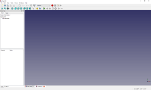
Fig 1: Freecad Open SheetFig 2: Freecad New Sheet Open FreeCAD. Click on the ‘File’ tab and select ‘New’.
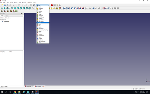
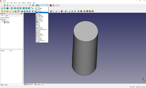
Fig 3: Part Selection Drop Down Menu Click on the drop-down box where it says ‘Start’ and select ‘Part’.
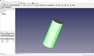
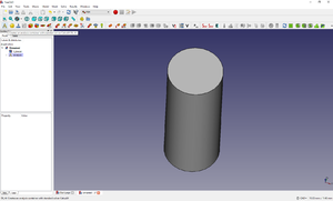
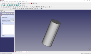
Now click on the cylinder symbol to generate a cylinder. You can rotate the object with help of scroll button on the mouse. Fig 4: Cylinder Data Selection
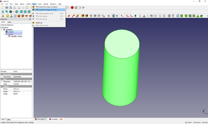
Select the curved surface of the cylinder. The cylinder dimensions can be edited in the Property-Value table on the left. For this tutorial, we take the default values (Radius = 2 mm, Height = 10 mm, Angle = 360) Fig 5: Dimension Selection Cylinder Data
Click on the drop-down box again and select ‘FEM’. This will turn on the analysis solver. Fig 6: FEM Window Selection
Click on ‘A’ under the drop-down box. Fig 7: A icon Selection
Select the curved surface of the cylinder and then click on the ‘Mesh’ tab to select ‘FEM Mesh by Gmsh’. Fig 8: Mesh Selection Window
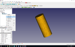
Enter the maximum element size as 0.5 and hit ‘Apply’ and ‘Ok’. The mesh might be hidden. To show the mesh, right click on the ‘FEMMeshGmsh’ in the model window and click on ‘Show Selection’. Fig 9: Mesh Selection WindowFig 10: Mesh Show Selection
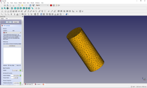
For adding the material, click on the ‘Model’ tab and click on ‘FEM Material for Solid’. Alternatively, you can click on the yellow circle right next to analysis button. You can select from the list of materials or give your own specifications for a material such as Young’s Modulus, Density and Poisson’s Ratio. For this tutorial, we select ABS. Press Ok. Fig 11: Material Selection
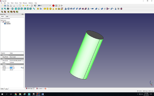
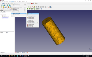
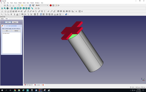
For adding constraints, click on the ‘Model’ tab and go to ‘Mechanical Constraints’ and then ‘Constraint fixed’. Select one circular face of the cylinder and click ‘Add’. Then click ‘Ok’ to exit. Fig 12: Material Constraint SelectionFig 13: Constraint Selection
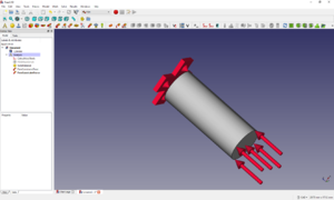
For Force constraint, again go to ‘Mechanical Constraints’ and click ‘Constraint force’. Select the other circular face of the cylinder. Enter the area load as 100 and press ‘Ok’.Fig 14: Force Selection
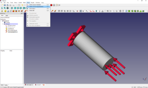
Select ‘CalculiXccxTools’ in the model window. Now click on ‘Solve’ tab and hit ‘Run Solver Calculations’. Fig 15: Solver screen
Double click on the ‘CalculiX_static_results’ and select the result you want on display.