
Designer[edit | edit source]
Petri Mustonen' Aalto University, Department of Electronics and Nanoengineering
Project[edit | edit source]
The polishing of copper foils is essential for high quality CVD graphene growth. The cold-rolling manufacturing process of these foils leave deep macro-sized striations on the foil surface, as well as numerous micro-sized defects. Generally these striations and defects are removed by using electrochemical polishing process. Even though this is easy to do manually, as the foil size is scaled up then the bending of the foils becomes a problem. The electrodes should be as straight as possible to ensure constant current density along the foil which is needed for smooth polishing process.
This project is meant to be used as a tool for keeping the foils straight as well as allow to change the distance of the electrodes easily. The model is made by OpenSCAD and is highly customizable.
NOTICE! You need to check the chemical stability of your printing material! I suggest starting with Polypropylene (PP) and Fluorinated Ethylene Propylene (FEP) and to check whether they work for you.
This project is the final project of the author for the L3999 course of Fall 2017.
Design[edit | edit source]
Concept[edit | edit source]
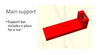
The entire structure is meant to be placed on top of a box in which the polishing process is done. The main support bar is merely a rectangular block on top of which is a slider. This slider is connected to a screw which is also attached to the main support bar, the slider is moved by rotating this screw. A secondary slider is pinned on one location of the support bar. Both sliders are connected to a frame. These frames have copper foil pinned in between them (a foil is pinned between two halves of the frame).
More detailed description in the video below.
Bill of Materials[edit | edit source]
- Base support bar
- Slider with screw support (referred to as "main slider")
- Slider without screw support (referred to as "secondary slider")
- Nut
- Screw
- Frame x 4 (each "frame" is only a half of the total frame)
- Slider-frame -attachment piece x 2
- Frame pins x 8 (attaching frames together)
- Slider pins x 2 (fastening the secondary slider to the main bar)
Estimated Cost[edit | edit source]
37g of PLA and 8g of PP (frame and attachment pins) =~$1.5 Using these materials: https://web.archive.org/web/20210617213737/https://gizmodorks.com/polypropylene-3d-printer-filament/ ~$62.5/1kg and https://web.archive.org/web/20220603014826/https://lulzbot.com/store/polymaker-polylite-pla-filament $25/1kg. https://ecoreprap.com/filament/pla-filament/ $22/1kg
Directions[edit | edit source]
- Download scad and STL files from NIH repository . The default STL files can accommodate 5x5cm pieces of foil and the distance between the electrolyte and the bottom of the main support bar is 5cm. Notice that the default tolerances are for PLA!
- If no need to change parameters, use the STL files to print. If parameters need to be changed, use the list under section "Parameters" and then "Main parameters" list in each scad file. If more tuning is required look for parameters under "Fine tuning" in the scad files.
- Print! I would recomment using small layer height for attachment pieces (pins), frame, nut and screw (I used 0.1mm). The rest can be done with larger height (I used 0.2mm). Other variables are the default ones for Lulzbot mini with high detail print (found here) and the Lulzbot mini printer was also used.
Parameters[edit | edit source]
Numerous parameters are customizable, however, the most important ones are listed here:
support_and_slider.scad[edit | edit source]
- bar_length Length of the main support bar
- frame_hole_wr Wiggle room of the hole for the main support bar (width, height)
- pin_radius_wr and pin_slit_width_wr Wiggle room for attachment pin slots
frame.scad[edit | edit source]
- frame_size Outer dimensions of the frame (width, height, thickness)
frame_attach.scad[edit | edit source]
- pin_length Length of pins attaching slider to the frame
slider_screw.scad[edit | edit source]
NOTICE! Changes to SCREW LENGTH have to be done in the data-metric_cyl_head_bolts.scad file!
- screw_name Name of screw (from data-metric_cyl_head_bolts.scad file)
- threads Whether to render threads or not (rendering slows the preview quite a lot)
Possible problems and how to solve them[edit | edit source]
I would recommend that you first print the screw, nut and main slider to check that they all connect together well. The side of the nut which is towards the printing pad is possibly smaller and this might need fixing, I peeled small pieces off of the nut with a hobby knife until the screw went through well. I would recommend to do this and not to go for a larger nut as it is better if the seal is tight and the screw does not wobble. Regarding this, it is also better that the sphere on the end of the screw is tightly in the slot on the main slider. If this wobbles it can be hard to keep the foil completely vertical. If the nut is too loosely in its slot (it moves around), then you need to change the "nut_scaling" parameter in the "Fine tuning" parameters section of "support_and_slider.scad" file.
The attachment pieces (pins and the frame attachment) can have printing issues due to the small size, warping can be expected. For PLA printing I used wood glue to get better adhesion on the printing pad. A raft or a brim can be used as well, but I found out that the complete removal of these structures can be an issue. This issue might arise with the frames as well, but for me it didn't happen enough for it to be a problem.
It can be hard to properly pin the second slider to the main support with the slider pins. If this is the case, then you can either try to make the fit better or you can use a thin PLA piece (I used a piece of a frame) and push it in between the slider and the support bar. This will probably hold the slider in place much better.
Future improvements[edit | edit source]
- More robust way of attaching the secondary slider to the support bar (screw type perhaps)
- Removal of excess plastic
- Unifying the slider-frame -attachment piece and one side of a frame to one structure
3D model parts[edit | edit source]
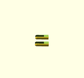
-
Attachment piece for attaching frame to sliders.
-
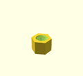
Nut for the screw.
-
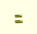
Pins for attaching secondary slider to the main support bar.
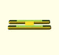
-
For pinning foil in between two halves of a frame.
-
For changing the distance between two sliders.
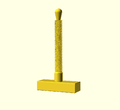
-

Slider to which the polished foil is attached to.
-
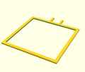
One half of a complete frame in between which the foil is pinned to.
-
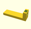
Main support bar for the entire structure.
-
Secondary slider for attaching second electrode.


Final Prints[edit | edit source]
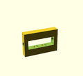
-
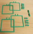
Frames, frame pins and slider pins.
-
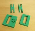
Sliders and frame-slider -attachment pieces.
-
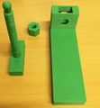
Main support bar, screw and a nut.
-
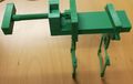
Full model.


