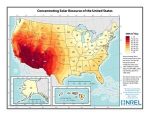
聚光太陽能發電(CSP)透過一系列陣列收集太陽的能量,然後將其集中或聚焦在陣列中心的位置。在這個中心點的能量變得非常熱,熱得足以熔化許多金屬並產生蒸氣。這些陣列中最引人注目的是大型定日鏡(鏡子)裝置,它們追蹤太陽並將輻射能量反射到高塔上的接收器。極少數較小的系統使用菲涅耳透鏡或拋物面反射器來集中太陽熱能。太陽能發電有很多優點
集中器設計
太陽能聚光技術有多種形式:
- 太陽能塔- 專為大規模集中式電網應用而設計。它們只是運行中的幾個原型,它們使用拋物面鏡反射太陽輻射,然後將其聚焦到位於反射器中心並高於地面的電力塔上。
- 碟式太陽能聚光器- 是電力塔的較小版本。鏡子陣列將太陽的能量集中在聚光器的中心。在 SES 和 SAIC 系統中,這是發電機組或發電機所在的位置。它們的功率範圍根據聚光器陣列的大小而變化,但 SES/SAIC 系統發電機的功率約為 20-40 千瓦時,足以為 4-6 個家庭供電。
- 太陽能槽- 通常設計為大型集中式電力系統的一部分,但它們不像電力塔那樣依賴集中焦點,可用於較小規模的應用。
- 高通量太陽能熔爐- 涉及地球表面太陽正常強度的許多倍的集中,產生非常高的溫度,從而能夠直接利用來自太陽的能量來成型金屬。
典型的系統可能由太陽追蹤器機電系統、熱能電池(有時稱為 TES 或熱能儲存)和應用程式(例如可以產生旋轉馬力的吸收裝置)組成。
定日鏡
定日鏡是一種包含鏡子(通常是平面鏡)的裝置,它可以轉動以不斷將陽光反射向預定目標,從而補償太陽在天空中的視運動。目標可以是遠離定日鏡的實體對象,或是空間中的方向。為此,鏡子的反射表面保持垂直於從鏡子看到的太陽方向和目標方向之間的角度的平分線。幾乎在每種情況下,目標相對於定日鏡都是靜止的,因此光線會沿著固定方向反射。
定日鏡的主要用途是用於採光(將日光引入原本照明不佳的空間)以及用於太陽能熱發電站的發電。它們也偶爾或過去曾被用於測量、天文學和其他科學領域,在太陽爐中產生極高的溫度,改善農業照明,並將持續的陽光照射到太陽灶上。在 19 世紀,畫家和其他藝術家使用它們來為他們的主題提供持續、明亮的照明。
定日鏡應與太陽追蹤器或太陽追蹤器區分開來,後者始終直接指向天空中的太陽。然而,某些類型的定日鏡包含太陽追蹤器以及用於平分太陽眼鏡目標角度的附加元件。
與太陽能光伏發電相比的優點和缺點
太陽能光電價格昂貴,與石油等其他能源相比,太陽能光電價格昂貴的原因之一是需要大量佔用大量面積的光電板才能產生一定量的電力。聚光太陽能雖然需要很小的佔地面積,因為它以更高的效率運行,每單位集熱器將更多的太陽光轉化為能量。然而,目前尚不清楚該技術的成本是否與光伏太陽能相比具有競爭力,更不用說石油或天然氣了,因為該技術仍處於實驗階段。目前,尚無能力大規模生產製造 SES 太陽能聚光器所需的零件,因此製造成本昂貴。SES 當然相信,一旦他們形成了規模經濟,建造這些陣列的成本將會大幅下降。
開發聚光太陽能技術的兩家主要公司均使用外燃機作為發電機組。然而,碟式太陽能係統的多功能性允許安裝不同的發電機組。內華達州 1MW 碟式太陽能引擎專案也位於 UNLV 測試設施內。對兩個碟式太陽能競爭對手 SAIC 和 SES 進行了相互評估。SES 似乎產生了更多的功率並且整體表現良好。然而,有趣的是使用三結太陽能電池創建的聚光太陽能/PV。這種混合動力有可能顯著增加電池容量,從而顯著提高電池的發電量,並減少發電所需的電池數量。但這仍然是一項實驗性技術。其他可能性包括使用熱電耦合或蒸汽渦輪機。
應用領域
SES 以其 1000 MW 斯特林發電機設施提出的集中式電力解決方案的大規模太陽能開發是實現再生能源經濟的選擇。
The Solar Power Village technology does fit this model and it also offers low-cost sterling engine solutions rather than high cost solutions put forward by SES. However SES's system may be more geared to produce electricity for sale to utilities than the Solar Power Village System. In one test performed by UNLV's solar research program SES's concentrator system outperformed SAIC's.
There are many other applications for industrial and human use of the latent heat stored in the TEB/TES
Why CSP?
Today's world suffers from an increasing dependence on fossil fuels, either for electricity production, transportation or reagent for the chemical industry. A technological revolution in hydrogen and electricity production is important to support the future needs and lead the world towards a better future. For that, technological and economical barriers have to be broken. Concentrated solar power (CSP) has been proving to be a valid means to start this revolution and produce electricity and hydrogen from completely renewable sources—water and the sun. Although solid steps should be taken to solve the current limitations and increase the technical and economical viability of these projects, there are conditions to begin this revolution using factual bridges from the current fossil technologies to renewable technologies.
Next steps
The most appropriate technology approaches are those focused on Distributed Power and/or District Power solutions and this primarily includes Dish and Trough solar Thermal systems. These systems are versatile, in that they can be used both in what are called distributed decentralized power systems and centralized, grid based or stand alone (off grid) applications (like the way most is generated today in large power plants at centralized locations.
Location
The world's first concentrated solar power tower (PS10) was built near Seville, Spain with construction beginning in 2004. The project today has 11 MW installed capacity, but the Spanish are aiming to increase installed capacity in the area to near 300 MW when other plants come online by the end of 2013.
The Ivanpah concentrated solar power plant in California's Mojave Desert is currently the world's largest such plant. The Ivanpah project has a planned installed capacity of 370 MW, although currently there are only 126 MW of installed capacity.
Solar power plants are preferred to be built in dry, arid regions of the world, which serve the dual purpose of maximizing solar insolation while protecting equipment from inclement weather. As with solar power in general, potential for CSP in the future is tremendous.
Solar CHP System Example
Solar insolation on Earth is tremendous and is more than capable of being a significant source of an energy portfolio. Consider that solar energy is responsible for plant growth, wind, waves, hydro-electric power, river power and direct conversion to electricity and for direct heat.
A major problem with CSP systems (and with any solar system) is matching load to supply. The storage of a hot liquid in the TEB, greatly in excess of the anticipated load over time, will allow for uninterrupted use. Critical backup should always be provided for hospitals, communication centers, and other essential services. The TEB can provide most of that backup, since heat can be generated and parsed into the TEB from a variety of sources (electric heat, liquid fueled heaters, geothermal heat, heat from biomass combustion). The supply of heat from the TEB allows for matching to a variable load. The use of solar radiance to heat the transfer liquid is the lowest cost source of energy, even considering the amortization of equipment and operational expenses. Distributed energy. The primary benefit is derived from the ability to size a system for a wide variety of different applications, loads, and locations. The Solar Furnace CHP System's electrical generation can operate in stand-alone mode or networked locally or nationally. A significant savings of energy lost over the transmission lines, due to heat radiation, can be realized by locating many smaller plants at the point of application and the avoidance of huge, centralized facilities.
Heat collection, storage and transfer. The use of a heat transfer liquid allows for two levels of heat. The collectors will be able, on a sunny day, to heat the liquid up to 600 degrees F. This liquid will be pumped to the TEB which is a large tank, heavily insulated and containing two heat exchangers. This tank can be made of many different materials, including temperature resistant concrete, ceramics, steel, aluminum, and other metals. The insulation will consist of a closed cell foam, made from soy, applied to the outside of the tank. The heat exchanger will be metal plate exchangers. Should one of the leaves of a plate exchanger fail, that exchanger can be unbolted and the failed plate replaced.
The tank takes its input from the solar collectors at the maximum temperature (not to exceed 600 degrees F), which incoming liquid heats the liquid in the TEB. A plate heat exchanger then parses that heat to the application. In doing so, the temperature of the liquid leaving the exchanger is regulated by a mixing valve which mixes the returning, colder fluid, with the outgoing hotter fluid, able to maintain the target temperature used by the application. Such mixing values are commercially available and can be linked to computer controls and remote sensors, switches, pumps and valves.
這些裝置將銷往農場、溫室經營、乳品廠、食品加工和包裝廠、工業工廠和機構。預計投資回收期為兩年到十年。
