Background[edit | edit source]
I am working with the Campus Center for Appropriate Technology (CCAT) on refurbishing their Mobile Energy Operation Wagon. It was stolen and vandalized, so the goal is to restore and improve its aesthetics and begin restoring it's operability. The outside has to get painted in a way that will represent CCAT. Solar panels need to get remounted and batteries need to be bought and installed if time allows. I will be working on this project during the 2012 spring semester and at the minimum, will have the MEOW's aesthetics restored and the solar panels mounted. I hope also install the batteries. I will be working at the Campus Center for Appropriate Technology, located on the HSU campus.
Problem statement[edit | edit source]
The objective of this project is to restore the Mobile Energy Operation Wagon. I will be making it look more attractive by painting it to better represent CCAT. At the minimum, the solar panels will also be reinstalled.
Evaluation Criteria[edit | edit source]
This section was created to weigh the amount of work and budget that goes into each aspect. The goal of this project is to restore CCAT's MEOW, paying special attention to aesthetics, so it can be modified for efficiency in a future project. I want to focus on durability, aesthetics and educational value as well as the obvious safety factor, so my project lays a good foundation for future projects.
| Criteria | Constraints | Weight (0-10) |
|---|---|---|
| Cost | must meet the budget | 7 |
| Safety | must be safe for everyone, especially since we're dealing with electricity | 10 |
| Maintainability | must be perform maintenance work on fairly easily, strive for simplicity | 7 |
| Durability | must be built structurally sound and built to last | 8 |
| Aesthetics | must be pleasant to look at | 9 |
| Efficiency | must be as least as efficient as the previous design | 7 |
| Operability | must be able to operate with one or two people | 8 |
| Educational Value | must be easily comprehensible upon first glance, and able to educate citizens in detail | 9 |
| Mobility | must be able to be transported, the lighter the better | 5 |
| Modular Expandability | must be able to adapt and expand for future design and improvement | 8 |
Literature Review[edit | edit source]
This is a review of literature that may be used to reference while working on CCAT's MEOW. My main focus on this project is mounting the photovoltaic panels, so my literature review will focus on the relevant subjects.
Photovoltaic basics[edit | edit source]
Photovoltaic systems consist of a photovoltaic generator (solar panel), power conditioning electronics, and storage facilities. A single photovoltaic panel that may be coupled with other panels to form a bigger system is called a module, and the finished system, an array. The panels consist of a frame, usually stainless steel or aluminum, and solar cells, which are lined with glass and backed with a polymer film. This allows maximization of light capture and keeps the temperature of the solar cells as low as possible to increase efficiency.[1] Photovoltaic panels present a pollution-free unlimited energy source, but are presented with a high cost for the cells, energy storage, and operating lifetime.[2] The panels I have available for this project are 4 REC Solar REC230PE panels. From the company's website, "REC modules have an industry leading energy payback time of one year. This is a result of innovations such as the new fluidized bed reactor (FBR) silicon production process which uses 80 to 90 percent less energy than traditional methods". Each panel weighs 39.6 lbs, and the dimensions are 65.50 x 39.02 x 1.50 inches.[3]
Photovoltaic concerns[edit | edit source]
Some concerns for this project are rack sturdiness, ability to achieve optimum tilt angle, and Energy Return on Investment (EROI). The group building the previous rack had problems with rack stability initially.[4] I will take this concern into account and build off of the previous mistakes and solutions. The tilt angle was previously difficult to reach at 30 degrees, and after discussing the project with CCAT, a big interest is building the rack so that it is capable of an even bigger tilt angle.[4] The final concern is for the EROI. Creating a positive ROI is not the goal of my project, but I may include the EROI into consideration when acquiring materials so a future project of creating a positive ROI is not made more difficult by my materials used.
Types of Panel Orientations[edit | edit source]
Solar panels may either be fixed or have some sort of tracking ability to follow the sun. CCAT has expressed a lot of interest in optimizing the tilt angle throughout various seasons, so that is where I will focus my research.
Fixed[edit | edit source]
The most efficient angle of a solar panel is facing directly at the sun. This can be determined by subtracting the latitude the panel is used at from 90 degrees, because the most efficient angle is the angle of latitude from vertical. In the summer, the optimal angle adds 15 degrees from the horizontal, and in the winter subtracts 15 degrees. Exact adjustments are not incredibly important because these 15 degree adjustments account for only 5% of the systems efficiency.[5] I subtract the latitude from 90 degrees because I will want to know the angle from the horizontal. Arcata lies at 40.9 degrees north; this gives an optimum year-round fixed angle of 49.1 degrees from the horizontal, a summer angle of 64.1 degrees, and a winter angle of 34.1 degrees.
1 or 2 Axis Tracking[edit | edit source]
Tracking systems are adjustable to "track" the sun throughout the day. A 2-axis tracking system, compared to a fixed tilt system increases the efficiency of the module 30-50%.[6] "For a nonconcentrating array, [a tracking system] is probably not worth the mechanical complexity involved, but if the array is portable, someone could turn it occasionally to face the sun."[5]
Horizontal[edit | edit source]
On cloudy days, energy capture comes from diffuse solar radiation, rather than direct sunlight. In this case, a panel with a fixed horizontal orientation captures up to 50% more energy than a 2-axis tracking system.[6] Eureka averages 188 days of cloudy cloud cover (coverage of 8/10 or more), based on daylight hours only.[7]
Costs[edit | edit source]
Because the goal of this project is to restore the trailer and get the panels mounted, I am only concerned with costs related to those components. The panels are already in possession, donated by David Katz of AEE Solar. The paint cost was based on an acquaintance of mine recently painting a short bus with spray paint. I tripled the cost the bus was painted for to allow flexibility and to ensure a lasting paint job. The reason I chose spray paint is that it is what the bus was painted with and I do not know much about brush on paint. The paint idea is open to suggestions. My main focus is on the rack. I am choosing to base my proposed budget on a Uni-Rac system plus some extra budget for something like a car jack I may end up using. The goal would be to mount the panels much cheaper. A past proposal for the MEOW project shows a possible 40% discount on a Uni-Rac system, this may be something that is looked into.
| Quantity | Item | Source | MSRP (each) ($) | Amount needed ($) |
|---|---|---|---|---|
| 4 | PV Panels | David Katz (AEE Solar) | 565.00 | 0.00 |
| 1 | Rack | Miscellaneous | 500.00 | 500.00 |
| 6 | Spray Paint (pack of 6) | Harbor Freight Tools | 36.00 | 216.00 |
| Total Cost | 716.00 | |||
- UPDATE: As of 4-12-12, the proposed budget is approximately $140. This is for the rack hardware. Painting is no longer planned on happening, but the trailer will be cleaned up. The rest of the project will be getting started installing components already in possession.
Proposed Timeline[edit | edit source]
March 2nd - A restoration/paint plan will be decided on
March 9th - Trailer aesthetics will be restored
March 19th - A racking system will be decided on
April 6th - Rack materials will be acquired
End of semester - Racking system/photovoltaic panels will be installed
Design[edit | edit source]
I am considering two design options. Placing all four panels on top would be bigger than the trailer slightly, which is the first option I am considering. The second would be to have two panels on the top of the trailer and two on the side that could be attached and adjusted through a hinge mechanism. The two images below are of trailer designs with panels mounted similar to these two MEOW options.
-
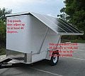
Example of top and side mounted panels with a hinge mechanism.
-
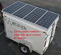
Similar to the previous MEOW rack design, all panels would be mounted on the top of the trailer.


- UPDATE: A mounting system solely to the top of the trailer has been decided on.
Description: Installation will begin by mounting 12.5' beams along the edges, lengthwise atop the trailer. These will be bolted to a wood/metal bracing already in existence inside the trailer on the ceiling. Mounted to each beam will be 8 T-shaped metal pieces with 3/8" holes drilled into them. In order for the T's to line up with the panels later in the installation, they will need to be installed in groups of 2, with the T's being 2' apart. Each pair will need to have a 15" gap between them. This will set the rack's hinge mechanism up.
Each panel will need 2 horizontal cross braces, each 3ft 3in long. Next, 6' L-beams already in possession will be mounted perpendicular to the horizontal cross braces with 3/8" holes drilled near each end. Two L-beams/panel will be used and each will need to be mounted 7.5" from the side of the panel as to give the 2' gap that will align with the T-braces mentioned earlier. The panels will then be ready to mount atop the trailer.
On the driver side of the trailer, the hinge mechanism will be a not-so-easily-removed simple bolt system(the 3/8" holes in the l-beams will be bolted to the 3/8" holes in the T-brace with 3/8" bolts). Next, a 3.5' length of square beam not yet in possession will need 3/8" holes drilled in each end. Then, each end of the 3.5' square beam will attach to the trailer T-brace and the panels' L-beams with 3/8 pins. Using a right angle triangle will prove a 3.5' beam will give the panels a 40degree tilt. The pins will provide for easy adjustment, and to lock the panels down for transport, it will be simple to remove the pins, store the beams, and lock down the panel straight to the T-brace.
If multiple tilt angles are of interest, a 4.5ft beam will give a tilt angle of 55degrees, and a 2.3ft beam will yield 25degrees.
Inventory[edit | edit source]
Have[edit | edit source]
- 2- 12.5' Beams
- 16- T-pieces (inadequate strength)
- 8- 6' L-beams
- 9- Pins
- Plenty of bolts, nuts, misc hardware
- All the MEOW trailer components
Need[edit | edit source]
- 26' Horizontal cross brace
- 32' Square beam (to give panels the tilt)
- 7 more pins
- 16 T-pieces of adequate strength
Work accomplished to date[edit | edit source]
- A solar pathfinder reading was taken and calculations were done(see following section)
- Painting was determined not to be a priority later in the semester as the goals of the project shifted. Multiple cleanup attempts were attempted however(paint thinner, sanding, scrubbing in the rain...) but all of these failed to my suprise. I believe the only way to clean up the trailer is going to be with an additional layer of paint added.
- Many trips were taken to acquire the materials needed for this project, but the semester is over and some crucial materials were never acquired. All the hardware such as bolts, nuts and pins were acquired without difficulty, but trips to the scrapyard to obtain brace material and the search for T-pieces presented great difficulty.
- A design which I believe is ideal was created after collaboration with other students as well as a trip to examine another existing mobile energy trailer in town.
- To save cost, I spent a great deal of time attempting to incorporate pieces from the previous rack into the design. Many pieces were cut and/or bolted together to become useful. After a trip from the metalyard a seemingly endless number of cuts turned an I-beam into over 16 T-pieces(of inadequate strength...).
- Not part of this project but closely related is that Nick Riedel at CCAT was successful in obtaining an inverter that can be tied into the grid as well as ordering batteries.
Calculations[edit | edit source]
A solar pathfinder reading was taken atop the trailer in the parking spot where it will be stationed and this data was combined with average daily insolation values for the different months taken from the PV Watts website. The following list shows how many kWh will be generated on average, daily in each month for the entire trailer system.
- January - 1.84 kWh/day
- February - 2.09 kWh/day
- March - 2.62 kWh/day
- April - 3.80 kWh/day
- May - 4.60 kWh/day
- June - 4.46 kWh/day
- July - 4.66 kWh/day
- August - 3.48 kWh/day
- September- 3.26 kWh/day
- October - 2.33 kWh/day
- November - 1.94 kWh/day
- December - 2.02 kWh/day


Problems and Pitfalls[edit | edit source]
Many problems were encountered during this project that I did not expect. I underestimated how quickly I needed to deal with each problem and I did not expect to run into another problem every time I fixed one. The majority of the difficulties lied in acquiring rack materials. I did not expect this to take so long, so I spent too much time in the planning and not implementing stage of the project.
One example of a problem was that I did not expect to have to mount horizontal cross beams before mounting the L-beam to the photovoltaic panels. I did not examine the amount of panel material I had to bolt into close enough and just assumed that I would bolt it without difficulty. As it turned out, when I did go to bolt it, the material was not wide enough for a bolt, so this required me to mount horizontal braces to the sides of the panels that were thick enough to bolt. After that, I could not find any suitable horizontal brace material after searching hardware stores and the metalyard.
The same thing goes for the T-pieces. I underestimated how difficult it would be to find certain metal joint pieces, and after being unable to find what I needed I attempted to make them out of scrap metal from the metal yard, which after being cut were not thick enough for me to be comfortable mounting the rack on.
I have not done a project like this before and realize I need to attempt to solve problems more quickly as it is likely to run into another problem immediately afterwards.
References[edit | edit source]
- ↑ Solar Power Systems: ECE Energy Series No. 11. New York: United Nations, 1993.
- ↑ Bube, Richard and Fahrenbruch, Alan. Fundamentals of Solar Cells. New York, Academic Press, 1983.
- ↑ Solar Electric Supply, Inc, 2011. http://www.solarelectricsupply.com/solar-panels/26/RECSolar_REC240PE-USBLK.html.
- ↑ 4.0 4.1 Scott and Yvonne, 2005. Appropedia. https://www.appropedia.org/CCAT_MEOW_rack.
- ↑ 5.0 5.1 Komp, Richard. Practical Photovoltaics. Michigan: aatec publications, 1995.
- ↑ 6.0 6.1 Kelly, Nelson, and Thomas Gibson. 2009. Improved Photovoltaic Energy Output for Cloudy Conditions with a Solar Tracking System. Solar Energy. 83, no. 11: 2092.
- ↑ http://web.archive.org/web/20170620071102/http://www.wrcc.dri.edu:80/htmlfiles/westcomp.ovc.html