
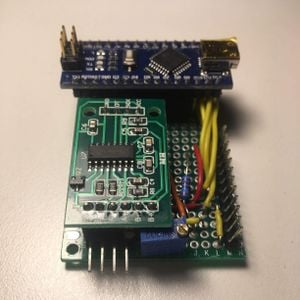
This OSAT is a digital mass balance with two outputs: Digital output for data logging capabilities, and an LCD display. This has value in several different areas, including pharmaceutical use (weighting out medicines) and scientific uses (such as 3D printing quality verification). This balance is powered and controlled by an Arduino Nano. Using the digital I/O pins, the Nano powers and reads information from an HX711 32-bit load cell amplifier. The readout from this loadcell can be calibrated using a standard mass. Calibration mode is entered using a push button. When connected to the Nano over serial (115200 baud), the raw (tared) and calibrated readout are displayed. Depending on the SSH client in use, this data can be logged and plotted - primarily for scientific uses. When an LCD is included in the system, the calibrated value is displayed with units.
For an updated version see Open Source Digitally Replicable Lab-Grade Scales.
Lovingly referred to as the OS Nano Balance
Bill of Materials[edit | edit source]
- 3D Printed Components (available along with source code on Github)
- 3D Printed Base - contains electronics, holds load cell, receives face.
- 3D Printed Bed - attaches to load cell, accepts items to be weighed.
- 3D Printed Face - contains tare button and optional LCD.
- 2 x 25mm M4 screws - available at a hardware store for pennies
- 2 x 25mm M5 screws - available at a hardware store for pennies776
- Arduino Nano - controller. A Nano Every is available for $10. Bootleg/copycat Nanos can be found on ebay for as low as $1
- Load Cell - currently designed for TAL220. TAL200s are available at SparkFun and Digikey. This Amazon vendor offers the TAL220 with an HX711 for $8.50. These load cells come in various load capacities and widely ranging prices, so shop around!
- HX711 - Load cell amplifier. This will ship with most low-cost load cells, but can also be purchased from Sparkfun for $10 (this is overpriced).
- Display
- 1602 LCD - Be sure to purchase a 5V compatible display! Available with Documentation on Sparkfun for $17, but any display will work (Amazon has cheaper options).
- 220 ohm resistor - Available in this kit for $8.
- 2k-10k ohm potentiometer - I used a Bochen 3296 W202 (2k ohm). These can be found on Digikey for $4, but come in bulk at lower cost.
- Assorted Circuit Components
- 4x6cm breadboard - These are the dimensions that the base is made to accommodate. The 6cm can be increased if desired. Similarly, a solderless breadboard could be used, but would need to be external to the balance. These come in large packs for around $7 on Amazon.
- Male and female headers. These are available on Adafruit for around $1 per set of headers.
- Jumper wires. Available on Adafruit for around $2
- An potentially simpler alternative to these is simply 22 AWG wire ($15 for far more than you'll need) and molex connectors (a few dollars for the amount necessary)
Tools needed[edit | edit source]
- MOST Delta RepRap or similar RepRap 3-D printer
- Soldering Iron and Solder (if using a solder breadboard)
- Tool for tightening M4 and M5 bolts. (I used 3mm and 4mm allen key drives; these may also be phillips, flathead, or hex drives)
- Computer with Arduino IDE installed
Skills and knowledge needed[edit | edit source]
- Soldering (if using a solder breadboard) - Youtube Tutorial, Wikiversity
Technical Specifications and Assembly Instructions[edit | edit source]
3D Printing[edit | edit source]
3 - 6 hours print time, depending on print quality desired
- Print with the quality level that is right for you. Aesthetics are generally not necessary for these components, so all of the parts can be printed (with 100% infill) in around 3 hours. Higher quality prints could take closer to 7 hours.
- Parts have large tolerances built in for bolts and screws, so fit should not be a problem.
Electronics Assembly[edit | edit source]
1 - 2 hours, depending on skill level and whether components come with headers installed
- Follow the Wiring Diagram. This can be accomplished on a solderless breadboard before committing to soldering.
- Be sure to design so the Nano's USB port will be accessible via the slot on the base.
- Be sure to put the tare button in the face plate prior to soldering it in place!


Mechanical Assembly[edit | edit source]
5 - 10 minutes, depending on print cleanup/reaming required

Attach the load cell to the base using the two M5 screws.

Snap the LCD into the face plate (the button should already be installed), and attach the face plate to the base.

Place the electronics in the base with the USB port on the Nano aligned with the slot on the right side of the base.

Attach the bed to the load cell using the two M4 screws.
Use[edit | edit source]
- Power up the balance by plugging 5 Volts into the Nano's USB port.
- On your first use, you will have to upload OS_Nano_Balance.ino to the board. This script and support libraries are available on Github. If you've never uploaded to an Arduino before, follow the instructions here
- Calibration is currently designed to be done with a cup of water at 20 deg C. It's not the most accurate, but it's accessible.
- Enter calibration mode by hitting the calibrate button.
- Allow the balance to tare with an empty container on the bed.
- Add 1 US cup of water to the container.
- Once the value has settled, hit the calibrate button again.
- Calibration is stored in the hard memory, so it should not need to be completed again.
Common Problems and Solutions[edit | edit source]
- Be sure your wiring is correct.
- Note that the power for the HX711 and the LCD come from the digital pinouts on the Arduino. If issues arise with getting power to these, use the 5V pin instead.
- If the LCD is not displaying, first check for power by viewing it in a dark room - is the LED backlight on? If so, change the potentiometer to both extremes. I've found that a rather small range of resistances actually causes the display to show up.
Cost savings[edit | edit source]
- The cost of this comes in around $20, depending on where parts are sourced. This matches the precision of a $120 lab-grade balance for about 17% of the price.
Benefited Internet Communities[edit | edit source]
References[edit | edit source]
- The sources of information (e.g. engineering handbooks, journal articles, government documents, webpages, books, magazine articles etc.). References should use the and <references />tags and can be in any format but should include all the information necessary for someone else to find the same information you did. For example:[1]
- ↑ web page: Department of Energy (DOE) Landscaping and Energy Efficiency, DOE/GO-10095 (1995) Available: http://web.archive.org/web/20021201231338/http://www.eren.doe.gov:80/erec/factsheets/landscape.html